Leon Mk1
| Input shaft: adjustment |

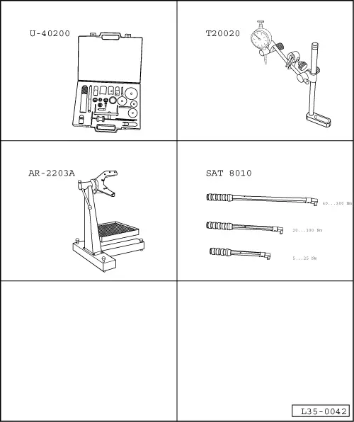
| Special tools and workshop equipment required |
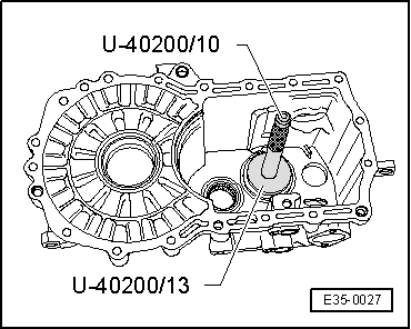
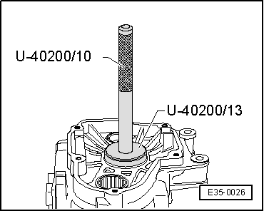
| t | Gearbox repair set -U-40200- |
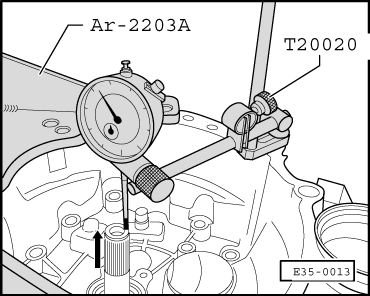
| t | Universal dial gauge bracket -T20020- |
| t | Gearbox-differential support column -AR-2203A- |
| t | Torque spanner -SAT 8010- |
|
|

|
 Note!
Note!
 Note!
Note!
|

|
| Bearing play | Shim | |
| Measured dimension (mm) | Thickness (mm) | No. of spares |
| 0.671 ... 0.699 0.700 ... 0.724 0.725 ... 0.749 | 0.650 0.675 0.700 | 02A 311 140 02A 311 140 A 02A 311 140 B |
| 0.750 ... 0.774 0.775 ... 0.799 0.800 ... 0.824 | 0.725 0.750 0.775 | 02A 311 140 C 02A 311 140 D 02A 311 140 E |
| 0.825 ... 0.849 0.850 ... 0.874 0.875 ... 0.899 | 0.800 0.825 0.850 | 02A 311 140 F 02A 311 140 G 02A 311 140 H |
| 0.900 ... 0.924 0.925 ... 0.949 0.950 ... 0.974 | 0.875 0.900 0.925 | 02A 311 140 J 02A 311 140 K 02A 311 140 L |
| 0.975 ... 0.999 1.000 ... 1.024 1.025 ... 1.049 | 0.950 0.975 1.000 | 02A 311 140 M 02A 311 140 N 02A 311 140 P |
| 1.050 ... 1.074 1.075 ... 1.099 1.100 ... 1.124 | 1.025 1.050 1.075 | 02A 311 140 Q 02A 311 140 R 02A 311 140 S |
| 1.125 ... 1.149 1.150 ... 1.174 1.175 ... 1.199 | 1.100 1.125 1.150 | 02A 311 140 TT 02A 311 140 AA 02A 311 140 AB |
| 1.200 ... 1.224 1.225 ... 1.249 1.250 ... 1.274 | 1.175 1.200 1.225 | 02A 311 140 AC 02A 311 140 AD 02A 311 140 AE |
| 1.275 ... 1.299 1.300 ... 1.324 | 1.250 1.275 | 02A 311 140 AF 02A 311 140 AG |
| 1.325 ... 1.349 | 1.300 | 02A 311 140 02A 311 140 |
| 1.350 ... 1.374 | 1.325 | 02A 311 140 02A 311 140 A |
| 1.375 ... 1.399 | 1.350 | 02A 311 140 A 02A 311 140 A |
| 1.400 ... 1.424 | 1.375 | 02A 311 140 A 02A 311 140 B |
| 1.425 ... 1.449 | 1.400 | 02A 311 140 B 02A 311 140 B |
| 1.450 ... 1.474 | 1.425 | 02A 311 140 B 02A 311 140 C |
| 1.475 ... 1.499 | 1.450 | 02A 311 140 C 02A 311 140 C |
| 1.500 ... 1.524 | 1.475 | 02A 311 140 C 02A 311 140 D |
| 1.525 ... 1.549 | 1.500 | 02A 311 140 D 02A 311 140 D |
| 1.550 ... 1.574 | 1.525 | 02A 311 140 D 02A 311 140 E |
| 1.575 ... 1.599 | 1.550 | 02A 311 140 E 02A 311 140 E |
| 1.600 ... 1.624 | 1.575 | 02A 311 140 E 02A 311 140 F |
| 1.625 ... 1.649 | 1.600 | 02A 311 140 F 02A 311 140 F |
| 1.650 ... 1.674 | 1.625 | 02A 311 140 F 02A 311 140 G |
| 1.675 ... 1.699 | 1.650 | 02A 311 140 G 02A 311 140 G |
| 1.700 ... 1.724 | 1.675 | 02A 311 140 G 02A 311 140 H |
| 1.725 ... 1.749 | 1.700 | 02A 311 140 H 02A 311 140 H |
| 1.750 ... 1.774 | 1.725 | 02A 311 140 H 02A 311 140 J |
| 1.775 ... 1.791 | 1.750 | 02A 311 140 J 02A 311 140 J |
|
|

|
 Note!
Note!
|

|
