
Leon Mk1
| Layshaft: dismantling and assembling |
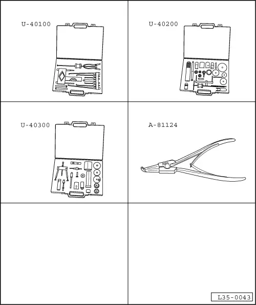
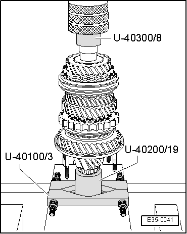
| Special tools and workshop equipment required |
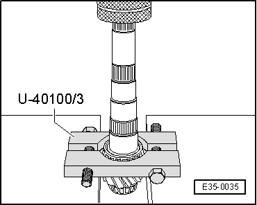
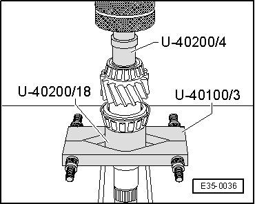
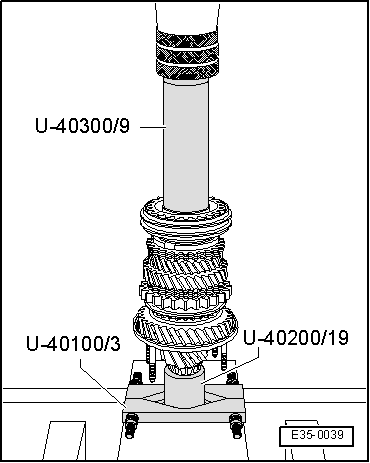
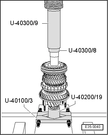
| t | Gearbox extractor set -U-40100- |
| t | Gearbox repair set -U-40200- |
| t | Gearbox repair set -U-40300- |
| t | Circlip opening pliers -A-81124- |
 Note!
Note!| t | Whenever new gears or a new layshaft are fitted consult the technical data → Chapter, Code letters, group numbers, ratios, filling quantities. |
| t | If the layshaft or the roller bearings are replaced, the layshaft must be adjusted → Chapter. |
| t | The layshaft must be adjusted whenever elements have been replaced which could affect the position of the roller bearings. Refer to Adjustment chart → Chapter. |
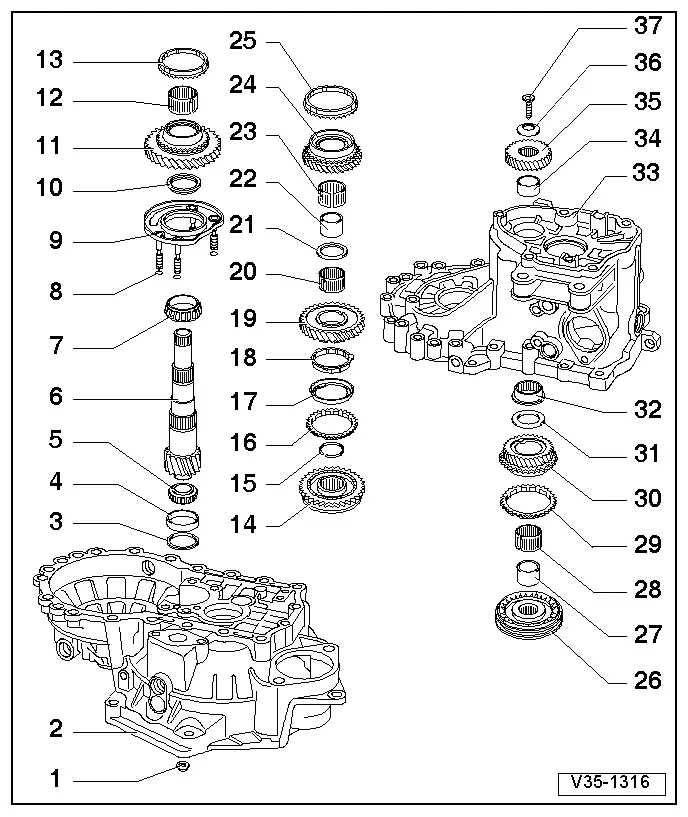
| 1 - | Hexagon nut |
| q | 25 Nm + 90° |
| q | 4 units |
| q | To secure the bearing housing |
| 2 - | Clutch housing |
| q | Repairing → Chapter |
| 3 - | Shim |
| q | For the layshaft |
| q | Determine thickness → Chapter, Layshaft: adjusting |
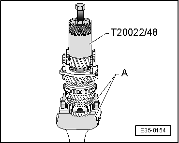
| 4 - | Outer track, roller bearings |
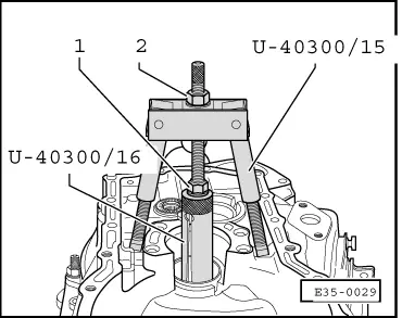
| q | Remove → Fig. |
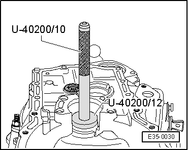
| q | Fit → Fig. |
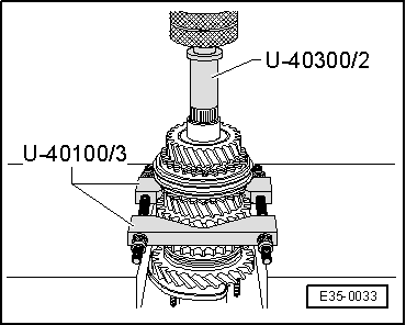
| 5 - | Small roller bearing |
| q | Remove → Fig. |
| q | Fit → Fig. |
| 6 - | Layshaft |
| q | A matched pair with the driveshaft gear; they must be replaced together |
| q | In case of replacement → Chapter, Code letters, group numbers, ratios, filling quantities |
| q | Adjusting → Chapter |
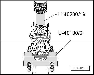
| 7 - | Large roller bearing |
| q | Remove → Fig. |
| q | Fit → Fig. |
| 8 - | O-ring |
| q | 4 units |
| q | Always renew |
| q | For the securing bolts of the bearing housing → Item |
| 9 - | Bearing housing |
| q | With outer track of the large roller bearing → Item |
| q | The external track should only be replaced together with the large roller bearing and the bearing housing |
| 10 - | Stop washer |
| q | The step of the shim should be facing the roller bearing |
| 11 - | Sliding 1st gear |
| q | Before fitting the 1st gear, fit the stop washer → Item |
| 12 - | Needle roller bearing |
| q | For the sliding 1st gear |
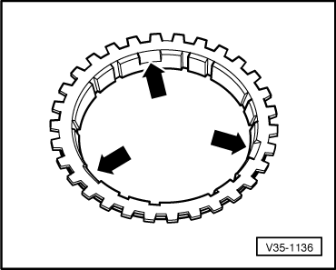
| 13 - | Synchronised ring for 1st gear |
| q | Identification → Fig. and → Fig. |
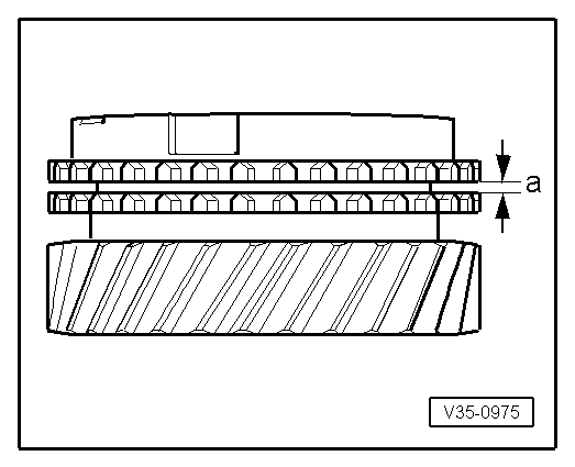
| q | Checking for wear → Fig. |
| q | Check that the tabs show no signs of wear |
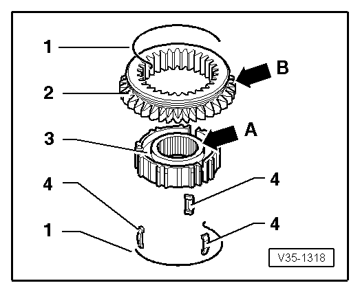
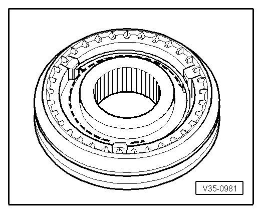
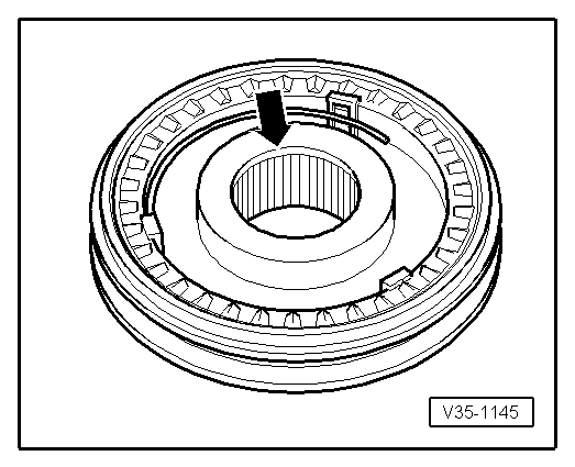
| 14 - | Syncromesh assembly for 1st and 2nd gear |
| q | Remove → Fig. |
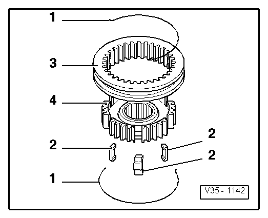
| q | Dismantling → Fig. |
| q | Assembling the components → Fig. and → Fig. |
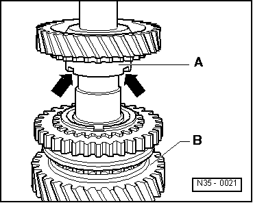
| q | Installation position → Fig. |
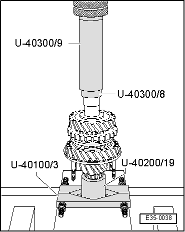
| q | Fit → Fig. |
| 15 - | Safety ring |
| q | Use tool -A-81124- to remove the circlip |
| q | Always renew |
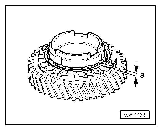
| 16 - | External syncromesh ring 2nd gear |
| q | Identification → Fig. and → Fig. |
| q | Checking for wear → Fig. |
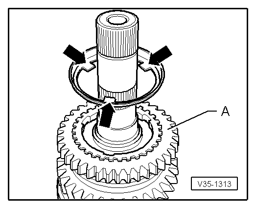
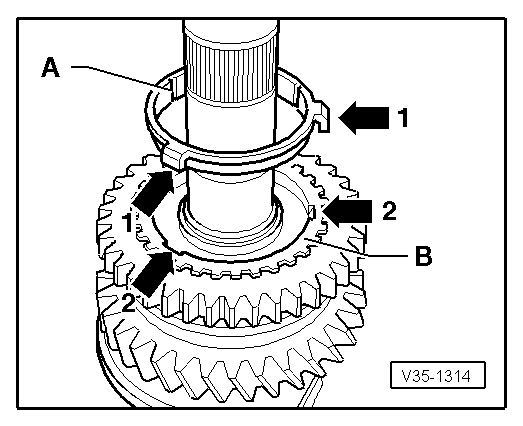
| q | Assembly position: The cut-outs of the syncromesh ring must fit with the locking keys in the 1st and 2nd gear syncromesh assembly → Item |
| 17 - | Intermediate syncromesh ring 2nd gear |
| q | Place in the external syncromesh ring 2nd → Item |
| q | Installation position → Fig. |
| q | Replace if it shows signs of wear or grooves |
| 18 - | Internal syncromesh ring 2nd gear |
| q | Identification → Fig. and → Fig. |
| q | Checking for wear → Fig. |
| q | Check that the tabs show no signs of wear |
| q | Installation position → Fig. |
| 19 - | Sliding 2nd gear |
| q | Installation position → Fig. |
| 20 - | Needle roller bearing |
| q | For sliding 2nd gear |
| 21 - | Stop washer |
| 22 - | Needle bearing bush |
| q | Remove together with sliding 2nd gear → Fig. |
| q | Fit → Fig. |
| 23 - | Needle roller bearing |
| q | For sliding 3rd gear |
| 24 - | Sliding 3rd gear |
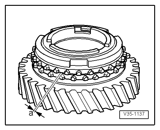
| 25 - | Syncromesh ring 3rd gear |
| q | Checking for wear → Fig. |
| 26 - | 3rd and 4th syncromesh assembly |
| q | Remove → Fig. |
| q | Dismantling → Fig. |
| q | Assemble → Fig. and → Fig. |
| q | Installation position → Fig. |
| q | Fit → Fig. |
| 27 - | Needle bearing bush |
| q | Remove together with the synchromesh 3rd and 4th gear assembly → Item |
| q | Fit → Fig. |
| 28 - | Needle roller bearing |
| q | For sliding 4th gear |
| 29 - | Syncromesh ring for 4th gear |
| q | Checking for wear → Fig. |
| 30 - | Sliding 4th gear |
| 31 - | Stop washer |
| 32 - | Needle roller bearing |
| q | For layshaft |
| q | Removing and fitting → Chapter, Gearbox casing and clutch casing: repairing |
| 33 - | Gearbox casing |
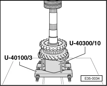
| 34 - | Needle bearing bush |
| q | Remove → Fig. |
| q | Fit → Fig. |
| 35 - | Sliding 5th gear |
| q | Removing and fitting → Chapter, Gearbox casing and 5th gear cover removing and installing |
| 36 - | Plate spring |
| q | Assembly position: the concave side should be facing the sliding 5th gear |
| 37 - | Securing screw for sliding 5th gear |
| q | The screw head incorporates a housing for the plate spring → Item |
| q | Assembly → Chapter,Gearbox casing and 5th gear cover removing and installing |
|
|
|
|
|
|
|
|
|
|
|
|
|
|
|
|
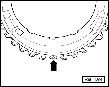
| Syncromesh ring | Measurement “a” on a new syncromesh | Wear limit |
| 1st gear 3rd gear 4th gear | 1.0 ... 1.7 mm | 0.5 mm |
|
|
|
|
|
|
|
|
|
|
|
|
|
|
| Syncromesh ring | Measurement “a” on a new syncromesh | Wear limit |
| 2nd gear | 1.2 ... 1.8 mm | 0.5 mm |
|
|
|
|
| Syncromesh ring | Measurement “a” on a new syncromesh | Wear limit |
| 2nd gear | 0.75 ... 1.25 mm | 0.3 mm |
|
|
|
|
|
|
|
|
|
|
|
|
|
|
|
|
|
|