seat Workshop Repair Guides

SEAT Workshop Service and Repair Manuals

Oil level for gears: checking > < Gear change: removing and installing
Installation
Installation
–  Fitting the diferential.
–  Fitting the layshaft.
–  Tighten the bolts of the bearing housing/layshaft.
   
–  Assembly position for the thrust washer of the 1st gear needle roller bearing:
–  The projection -A- in the internal diameter faces the bearing housing -B-.
–  Place the thrust washer , the needle roller bearing, the gear and the 1st gear syncromesh ring in their positions.
  V34-2571
–  Assembly position of the sleeve and 1st/2nd gear syncromesh:
–  The identification groove at the front -A- and the external teeth of the sleeve -B- face the 1st gear -C-.
  V34-2572
–  Heat the sleeve and 1st/2nd gear syncromesh to 100 °C approx. locate them and move to the end with tool -U-40200/20-.
–  Turn syncromesh gear so that the cut-outs coincide with the locking keys.
–  Fit the reverse gear, locking the shaft if necessary.
  E34-0014
–  Fit the needle roller bearing bush of the 2nd sliding gear -A- to the limit.
–  Fit the needle bearing, the syncromesh ring, the sliding 2nd gear and the 3rd gear.
  E34-0015
Assembly position of the 3rd gear
The collar -arrow- faces the 2nd sliding gear -A-.
–  Fit 3rd gear with the aid of tool -U-40200/20-.
  V34-2573
Adjust the axial play of the 3rd gear as follows:
–  Determine the thickest safety ring that can be used and fit it.
There are the following circlips:
  V34-1427
Spares No.Thickness (mm)Identification
020 311 3812.5brown
020 311 381 A2.6black
020 311 381 B2.7metallic white
020 311 381 C2.8copper
020 311 381 D2.9brass
020 311 381 E3.0blue

   
–  Fit the input shaft support -U-40007-.
  Note!
Check that the ball bearings for the input shaft are correctly seated, resting on the 4th gear.
–  The input shaft will rest on tool -U-40007-, previously fitted to the clutch casing. The input shaft will be slightly elevated.
  E34-0016
Assembly position of the 4th gear
The collar -B- faces the 5th gear teeth -A-.
–  Tilt the input shaft slightly on fitting the 4th gear and secure it with a new safety ring.
  E34-0017
–  Insert the lower spring of the control rod into the clutch casing -arrow-.
  V34-2465
–  Fit the fork assembly and line up the connection mouths.
-A- 1st and 2nd gear fork. The arrow indicates the recess for the connection bridge -C-
-B- 3rd and 4th gear fork
-C- Connection bridge with tube for 5th gear
-D- Reverse gear fork
–  Insert the control rod.
  V34-2575
–  Align the reverse gear shaft Dimensions -x- are identical.
–  Locate the magnet in its housing in the clutch housing. Secure with -AMV 188 200 03- paste.
–  Locate the retaining plate (support for input shaft bearing) in its position. There is only one assembly position.
–  Thoroughly clean the contact surfaces of the clutch housing and the gearbox casing. Apply a uniform layer (not too thick) of sealing paste -AMV 188 200 03-.
–  Fit the clutch housing to the gearbox casing. Check that the retaining plate (support for input shaft bearing) is in its position.
  E34-0018
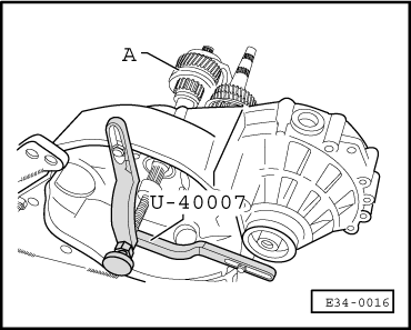
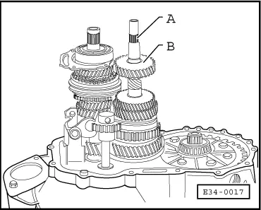
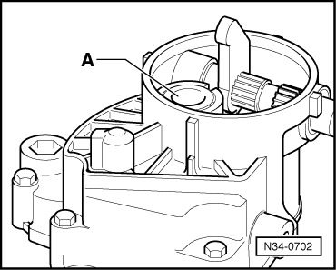
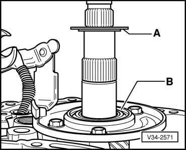
–  Fit an M7 bolt -1- longer than the originals, into the retaining plate The input shaft should be slightly above its position, resting on tool -U-40007-.
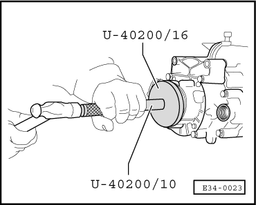
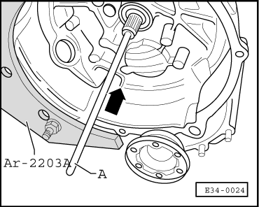
–  Hit the geabox casing lightly with the plastic hammer, holding the coupling rod at the same time, until the bearing is partially fitted.
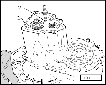
–  Fit the bolts -2- to secure the tensioning plate and take the gearbox casing to its position.
–  Fit the gearbox casing.
–  Loosen tool -U-40007- support so that the input shaft moves to its position.
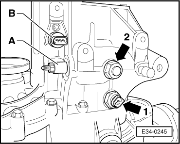
–  Bolt up the reverse gear shaft.
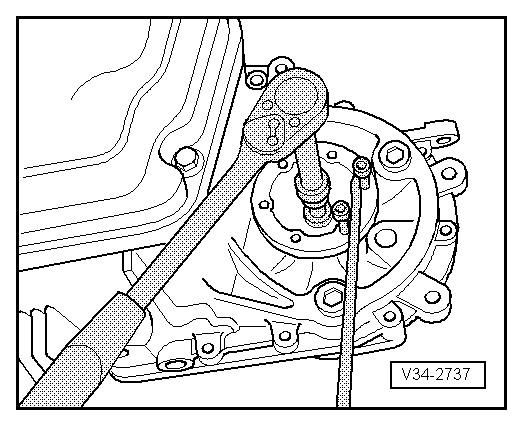
–  Tighten the hexagon bolts that secure the gearbox casing to 25 Nm.
–  Remove the M7 bolt from the ball bearing retaining plate.
–  Re-tighten the ball bearing retaining plate bolts to 15 Nm.
–  Fit the 5th gear.
  E34-0020
Assembly position:
The groove -arrow- should be facing upwards.
–  Fit the thust washer and the safety ring.
–  Fit the 5th gear syncromesh assembly with the sliding sleeve, the sliding gear and the 5th gear fork, as well as a new lock tab.
–  Introduce the connection tube into the gearbox fork by screwing it to the right with tool -U-40200/8-.
  E34-0021
–  Unscrew the connection tube until dimension -x- is attained. Dimension -x- = 5.0 mm.
  Note!
Do not remove the control rod from the connection tube (which can occur if you tilt the spanner, for example), because the forks would be released inside the gearbox and they would have to be re-assembled. If necessary, hold the control rod down inserting a screwdriver through the lateral groove on removing the box spanner.
–  Apply -D 000 600 A2- to the new bolt for the syncromesh and fit the syncromesh.
  V35-0752
–  Connect the 5th gear -arrow 1-.
–  Select reverse gear -arrow 2-, pushing the front connecting mouth down.
–  Unscrew the syncromesh bolt -arrow- with the XZN 12 mm spanner, from tool -U-40020-.
–  Place the gear stick in neutral position.
  V34-2552
–  Fit the gear selector shaft -1-.
–  Fit the compression spring -2- for the gear selector shaft and tighten the cover -3- with tool -U-20020-.
  Note!
If the cover had an oilseal -4- it will have to be renewed.
–  Apply -AMV 188 200 03- sealer to the locking bolt -5- of the selector rod and screw it into its place to 40 Nm.
Adjust the 5th gear fork as indicated below:
l  Adjust with the greatest of care to avoid “jumping out of gear”
  N34-1264
–  Make sure that dimension -x- of the connection tube lug is 5.0 mm and adjust it with tool -U-40200/8- if necessary.
–  Screw in the gear selector stick to the gear selector shaft and select 5th gear (pull out the shaft completely and turn left).
  V35-0752
–  Align the sliding sleeve -1- with the gear fork -2- so that there is no clearance with relation to the 5th gear -3-.
l  Measurement: The distance -a- between the sliding sleeve and the gear should be = 1.3 mm. If this value is not obtained, turn the connection tube to correct it.
–  Deselect 5th gear. The sliding sleeve should be in neutral position. The syncromsh ring must turn freely.
  N34-0414
–  Fit the new fixing plate with tool -T20131- and fit the bolt -arrow-.
–  Select all the gears one after the other.
–  Thoroughly clean the contact surfaces of the gearbox casing and the cap for the gearbox casing. Apply a uniform layer (not too thick) of sealing paste -AMV 188 200 03-.
  E34-0247
–  Fit the cap -arrow- of the gearbox housing (6 bolts) on the gearbox housing.
  Note!
t  One of the 6 bolts is under the cap.
  A34-0041
t  Fit the clutch release bearing -A- in the cap of the gearbox housing.
  N34-0702
–  Fit dust sleeve cover.
  Note!
The sealing surfaces of the gearbox lid must be totally free from grease.
  E34-0023
–  Fit both articulation flanges with the pressure springs, thrust washers and conical rings.
  V34-2737
–  Apply -AMV 188 200 03- sealer to the reversing light switch -arrow 1- and screw it into its place to 20 Nm.
–  Fit the control -B- of the speedometer.
–  Remove the input shaft support -U-40007-.
  E34-0245
–  Intorduce the clutch pushrod into the input shaft -A-. Assembly position of the clutch pushrod → Chapter, Clutch repairing.
  E34-0024

Oil level for gears: checking > < Gear change: removing and installing