
Leon Mk1
| Layshaft: dismantling and assembling |
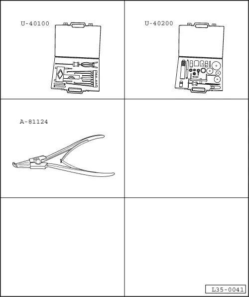
| Special tools and workshop equipment required |
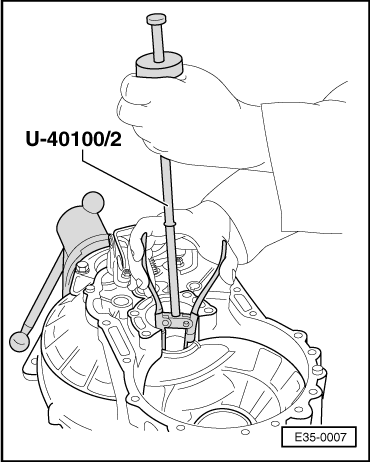
| t | Gearbox extractor set -U-40100- |
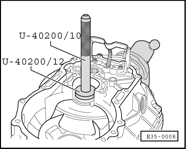
| t | Gearbox repair set -U-40200- |
| t | Circlip opening pliers -A-81124- |
 Note!
Note!| t | Whenever new gears are fitted consult the technical data → Chapter, Code letters, group numbers, ratios, filling quantities |
| t | If the layshaft, roller bearings or clutch housing are replaced, the layshaft should be adjusted → Chapter |
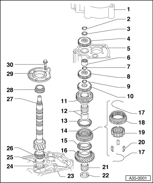
| 1 - | Gearbox casing cover |
| 2 - | 5th gear safety ring |
| q | Renew |
| 3 - | Thrust washer |
| 4 - | Sliding 5th gear |
| q | Fit → Chapter, Assembly sequence |
| 5 - | Gearbox casing |
| 6 - | Needle roller bearing |
| q | Removing and fitting → Chapter, Gearbox casing and gearbox selector shaft: repairing |
| 7 - | 4th gear safety ring |
| q | Renew |
| q | Use tool -A-81124- to remove the circlip |
| 8 - | 4th gear |
| 9 - | 3rd gear safety ring |
| q | Renew |
| q | Determine thickness → Chapter, Assembly sequence |
| q | Use tool -A-81124- to remove the circlip |
| 10 - | 3rd gear |
| q | Installation position → Chapter, Assembly sequence |
| q | Checking axial clearance → Chapter, Assembly sequence |
| 11 - | Sliding 2nd gear |
| 12 - | Needle bearing for sliding 2nd gear |
| q | Removing the bush → Chapter, Assembly sequence |
| q | Fitting the bush → Chapter, Assembly sequence |
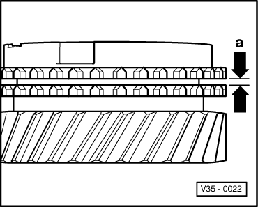
| 13 - | Syncromesh ring 2nd gear |
| q | Checking for wear → Fig. |
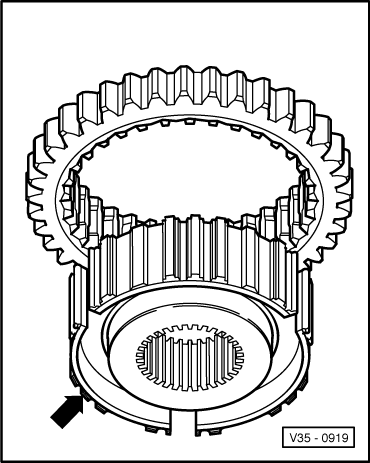
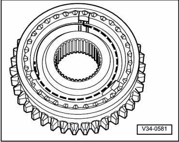
| 14 - | Syncromesh assembly for 1st and 2nd gear |
| q | Assembly → Fig. and → Fig. |
| q | Remove → Chapter, Assembly sequence |
| q | Fit → Chapter, Assembly sequence |
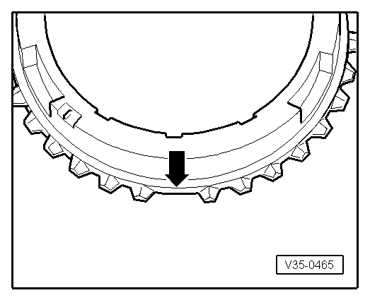
| 15 - | Syncromesh ring 1st gear |
| q | Checking for wear → Fig. |
| q | Identification → Fig. |
| 16 - | Sliding 1st gear |
| 17 - | Spring |
| 18 - | Sliding sleeve |
| 19 - | Syncromesh hub |
| 20 - | Locking keyways |
| q | 3 units |
| 21 - | Needle roller bearing for 1st gear |
| 22 - | Thrust washer |
| q | Installation position → Chapter, Assembly sequence |
| 23 - | Clutch housing |
| 24 - | Shim |
| q | For layshaft |
| q | Adjustment chart → Chapter |
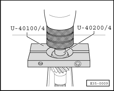
| 25 - | Outer track, small roller bearing |
| q | Remove → Fig. |
| q | Fit → Fig. |
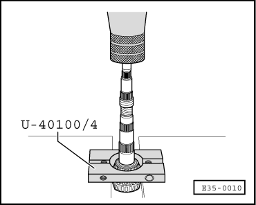
| 26 - | Small roller bearing |
| q | Remove → Fig. |
| q | Fit → Fig. |
| 27 - | Layshaft |
| q | A matched pair with the driveshaft gear; they must be replaced together |
| q | Adjusting → Chapter |
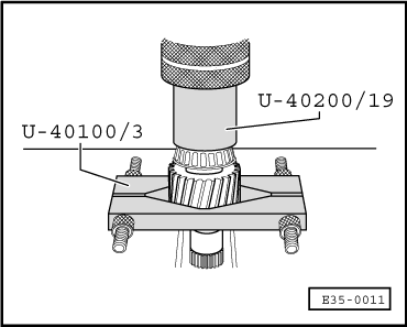
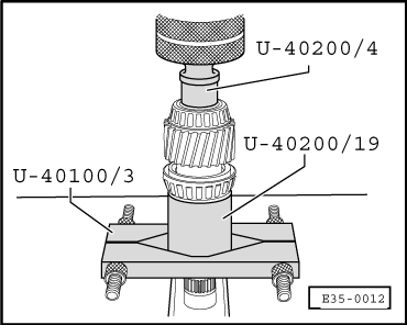
| 28 - | Large roller bearing |
| q | Remove → Fig. |
| q | Fit → Fig. |
| 29 - | Bearing housing |
| q | With the external roller bearing track and stop for reverse gear |
| q | The external track should only be replaced together with the large roller bearing and the bearing housing |
| 30 - | Hexagon bolt |
| q | 25 Nm + 90° |
|
|
| Syncromesh ring | Measurement -a- on a new syncromesh | Wear limit |
| 1st and 2nd gears | 1.1 … 1.7 mm | 0.5 mm |
|
|
|
|
|
|
|
|
|
|
|
|
|
|
|
|