
Leon Mk1
| Input shaft: dismantling and assembling |
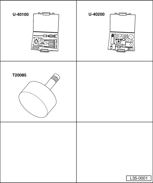
| Special tools and workshop equipment required |
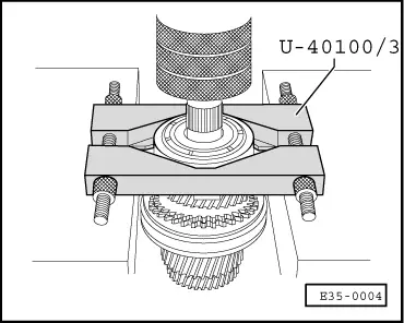
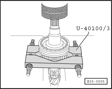
| t | Gearbox extractor set -U-40100- |
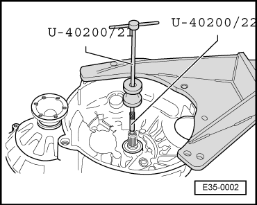
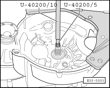
| t | Gearbox repair set -U-40200- |
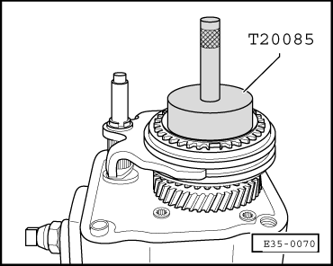
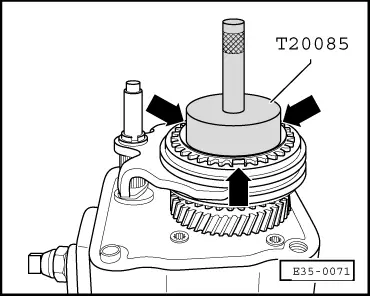
| t | Tool for removing/fitting stop ring 5th gear -T20085- |
 Note!
Note!| Whenever new gears are fitted consult the technical data → Chapter, Code letters, group numbers, ratios, filling quantities. |
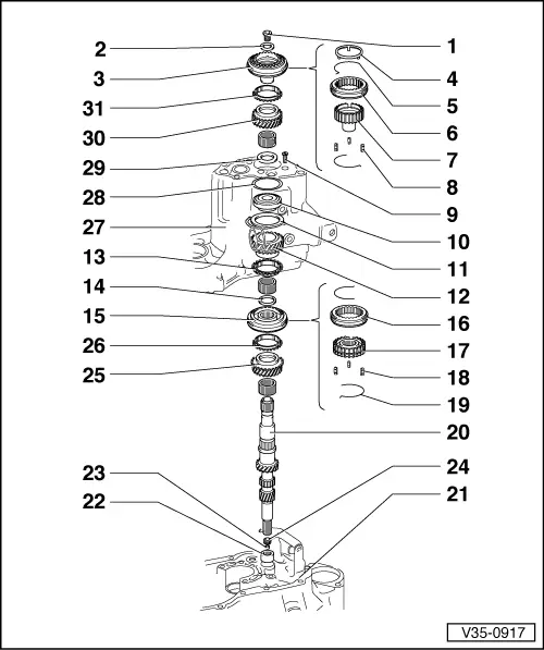
| 1 - | Bolt |
| q | 150 Nm |
| q | Renew |
| q | Removing and fitting → Chapter, Assembly sequence |
| 2 - | Plate spring |
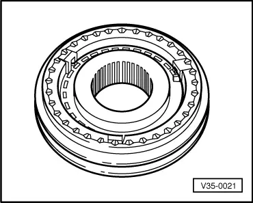
| 3 - | Syncromesh assembly 5th gear |
| q | Removing and fitting → Chapter, Assembly sequence |
| 4 - | Stop ring |
| q | Stops the locking keys from being released |
| q | Remove → Fig. |
| q | Fit → Fig. |
| 5 - | Spring |
| 6 - | Sliding sleeve for 5th gear |
| q | Installation position → Fig. |
| 7 - | Syncromesh hub 5th gear |
| 8 - | Locking keyways |
| q | 3 units |
| 9 - | Countersunk bolt |
| q | 15 Nm |
| q | M 7 x 23 |
| q | 4 units |
| 10 - | Ball bearing |
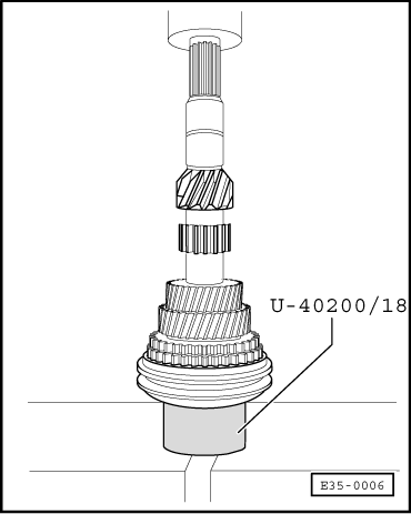
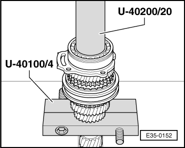
| q | Remove → Fig. |
| q | Installing → Fig. |
| 11 - | Fixing plate |
| q | Secures the ball bearing |
| 12 - | Sliding 4th gear |
| 13 - | Syncromesh ring for 4th gear |
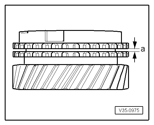
| q | Checking for wear → Fig. |
| 14 - | Safety ring |
| q | Renew |
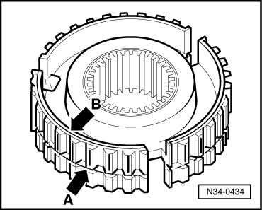
| 15 - | 3rd and 4th syncromesh assembly |
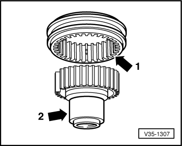
| q | Remove together with sliding 3rd gear → Fig. |
| q | Syncromesh installation position → Fig. |
| q | Assemble → Fig. |
| q | Fit → Fig. |
| 16 - | Sliding sleeve |
| 17 - | Syncromesh hub |
| 18 - | Locking keyways |
| q | 3 units |
| 19 - | Spring |
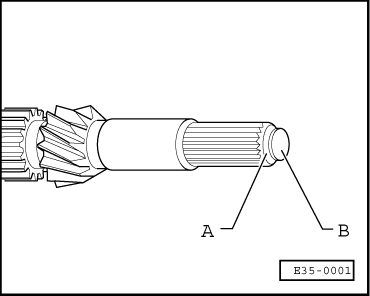
| 20 - | Input shaft |
| 21 - | Clutch housing |
| 22 - | Needle roller bearing |
| q | For input shaft |
| q | Removing and fitting → Chapter, Clutch housing: repairing |
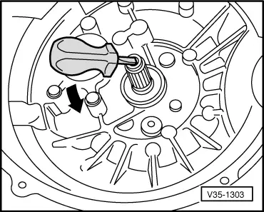
| 23 - | Oilseal for clutch pushrod |
| q | Can be replaced with the geabox removed (not dismantled) |
| q | Remove by levering with a screwdriver → Fig. |
| q | Installation position → Fig. |
| q | Fit → Fig. |
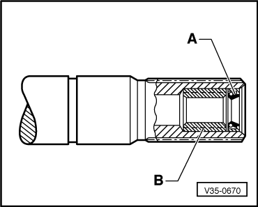
| 24 - | Bush for clutch pushrod |
| q | Can be replaced with the geabox removed (not dismantled) |
| q | Remove → Fig. |
| q | Installation position → Fig. |
| q | Fit → Fig. |
| 25 - | Sliding 3rd gear |
| 26 - | Syncromesh ring 3rd gear |
| q | Checking for wear → Fig. |
| 27 - | Gearbox casing |
| 28 - | Shim |
| q | For input shaft |
| q | See → Item |
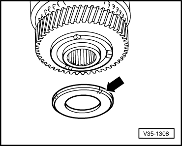
| 29 - | Thrust washer |
| q | Installation position → Fig. |
| q | Once the 5th gear syncromesh ring has been fitted, → Item, fit the sliding 5th gear, → Item, on the syncromesh hub → Item |
| 30 - | Sliding 5th gear |
| 31 - | Syncromesh ring 5th gear |
| q | Checking for wear → Fig. |
|
|
|
|
|
|
|
|
|
|
|
|
|
|
| Syncromesh ring | Measurement -a- on a new syncromesh | Wear limit |
| 3rd gear 4th gear 5th gear | 1.15 … 1.75 mm 1.3 … 1.9 mm 1.3 … 1.9 mm | 0.5 mm |
|
|
|
|
|
|
|
|
|
|
|
|
|
|
|
|