| Removing and fitting the synchromesh unit of 1st and 2nd gears |
| –
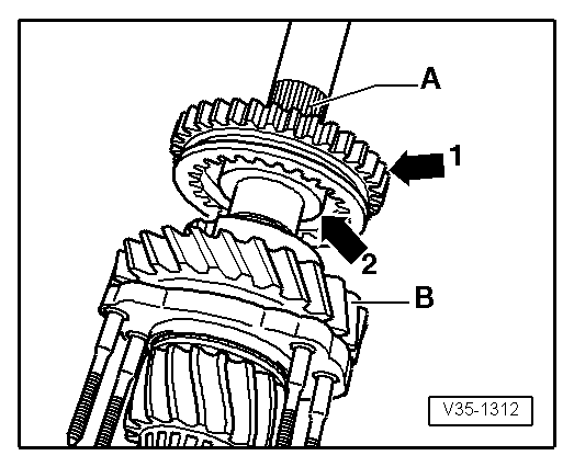
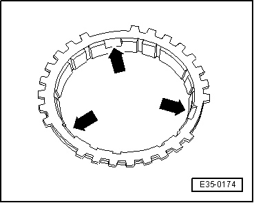
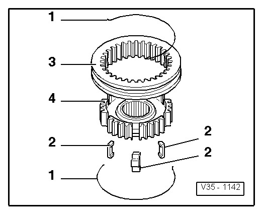
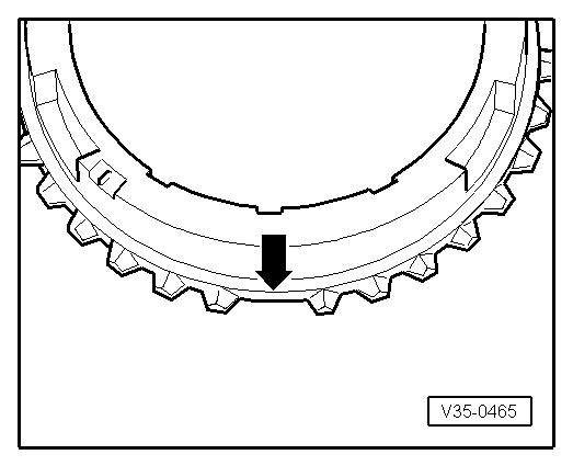
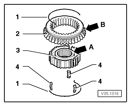
| To remove the synchromesh assembly of the 1stª and 2ndª gear, remove the springs -1- and move the sliding sleeve -2- completely upwards. |
| Install the 1st and 2nd gear synchromesh unit as follows: |
| –
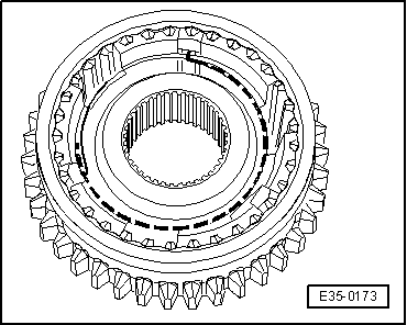
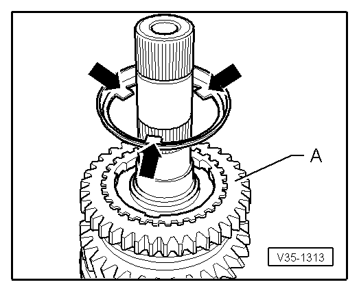
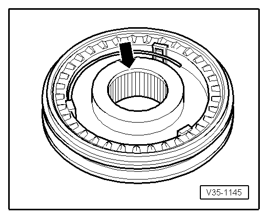
| Place the mobile sleeve -3- on the synchromesh hub -4-, so that the grooves for the locking pins -2- on both components coincide. |
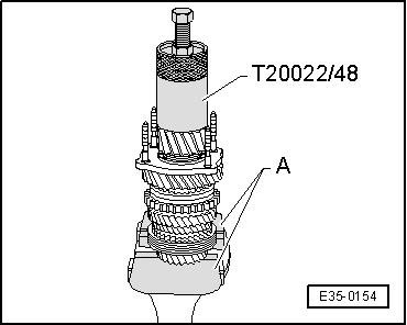
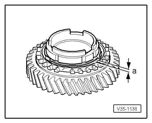
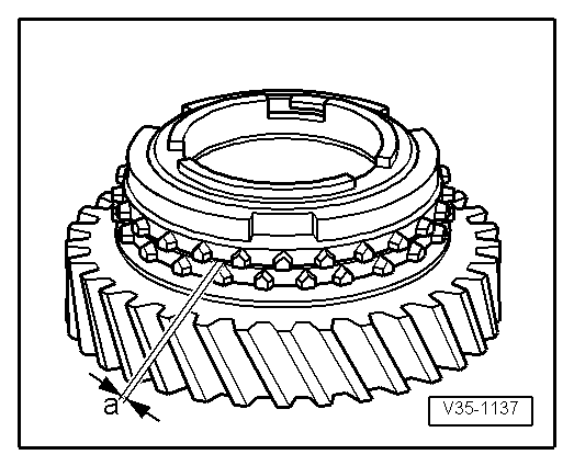
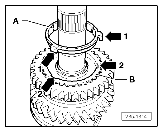
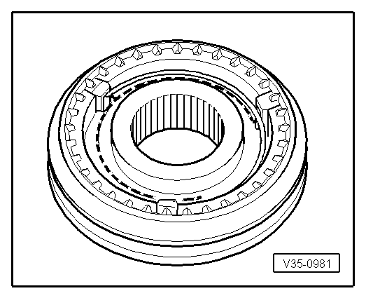
| Install the mobile sleeve on the hub, so that after assembly they are situated with the widest collar on the synchromesh hub -A-, and the outer cogs on the slide -B- facing opposite directions. |
|
|
|

 Note
Note