seat Workshop Repair Guides

SEAT Workshop Service and Repair Manuals

Reverse gear shaft: Disassembling and assembling > < Input shaft: Disassembling and assembling
Installing
Installing
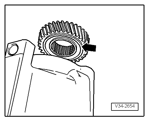
Installation position of 5th gear pinion:
   
–  The lobe present -arrow- on the internal diameter of the gear must be orientated towards the gearbox casing.
–  Heat 5th gear pinion to approx. 100 ºC with the hot air blower -SAT 1416-.
  V34-2654
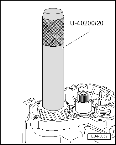
–  Press in sprocket with adapter -U 40200/20-.
  E34-0057
Check 5th gear synchro ring for wear.
–  Before checking for wear, thoroughly clean the synchroniser ring and 5th gear mesh.
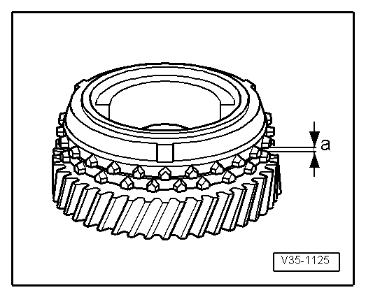
–  Fit 5th gear synchro ring on the mobile pinion. Press the synchro ring on the sprocket and measure the elevation „a“ with a thickness jig.
  V35-1125
Synchro-ringMeasurement „a“ on
new
synchromesh
Wear limit
5. gear1,1 ... 1.7 mm0.5 mm

–  Fit the mobile 5th gear pinion with the needle bearing.
–  Fit 5th gear synchro ring on the mobile pinion.
   
Install synchromesh assembly of 5th gear
  Note
Before fitting the assembly, check the synchromesh for wear
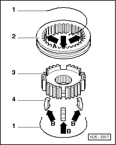
Install synchromesh assembly of 5th gear in the following way:
–  Place the mobile sleeve -2- on the synchromesh bush -3-, so that the grooves to house the locking pins -arrows A- on both components coincide -4-.
–  Install the locking pins -4-. Fitting position: the recess -arrow B- pointing toward sharp teeth on selector sleeve -2-
  N35-0017
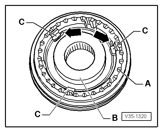
Install springs in synchromesh assembly of 5th gear
–  Install spring rings 120° offset below extensions -C-. Springs must seat with angled ends in front of locking pieces -arrows-.
–  Check that the teeth terminating in end -A- of the sliding sleeve are located in the same direction with the most pronounced lug -B- of the axle box.
–  Check that locking pins are correctly installed → Anchor.
  V35-1320
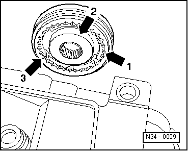
Installation position of the synchromesh unit / mobile sleeve of 5th gear
–  Install 5th gear wheel on input shaft so that the teeth on the conical selector sleeve -arrow 1- and the high collar on the synchromesh element -arrow 2- point toward the transmission housing.
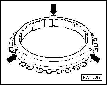
–  Align recesses -arrow 3- on synchromesh hub to locking elements on synchromesh ring (-arrows- lower figure).
  N34-0059
5th gear synchromesh ring with connected locking elements -arrows-
–  Cover all holes with rag to prevent foreign body from penetrating into the transmission.
  N35-0018
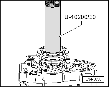
–  Fit synchromesh assembly on 5th gear mobile pinion. Use the adaptor - U 40200/20-.
  Note
When fitting synchromesh assembly to 5th gear, check the 5th gear synchromesh ring turns freely.
–  Clean bolt holes for mounting synchromesh element and 5th gear with tap to remove residues of bolt securing agent.
Otherwise the bolts may shear.
–  Partially screw mounting bolts → Item onto synchromesh element and 5th gear wheel.
  E34-0058
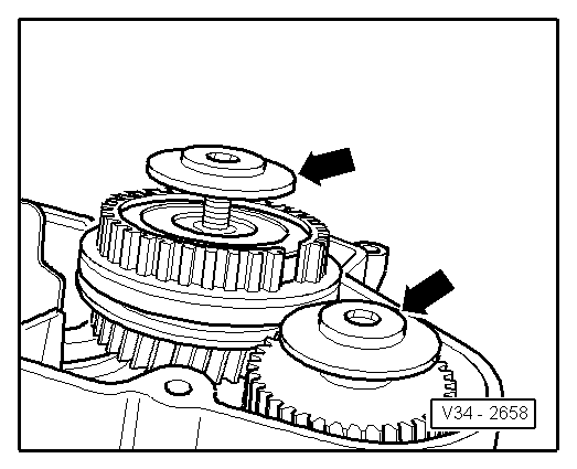
Installation position of the plate spring
–  The concave side of the plate springs -arrows- should point toward the synchronous hub and 5th gear wheel.
  V34-2658
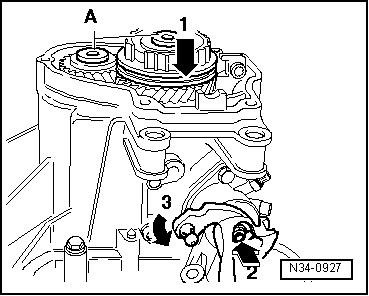
Before tightening mounting bolts on synchromesh hub and 5th gear wheel, press 5th gear selector sleeve downward -arrow 1- and engage gear. Also shift into 1st gear with shift lever -arrow 2- and -arrow 3-.
The input and output shafts remain locked when two gears are engaged; the synchromesh hub and 5th gear wheel do not turn. Tighten the bolts -A- to a torque of 80 Nm.
–  Install 5th gear connection prong with a torque of 25Nm.
  N34-0927
Adjust the sliding sleeve and the prong for the 5th gear
–  5. Gear engaged. Loosen bolt -1-. Press the mobile sleeve and the gear mouth in the direction of the -arrow-; then tighten the bolt -1- to 25 Nm.
l  Control measurement: Between the mobile sleeve and the mobile pinion, a thickness gauge of 0.2 mm cannot be inserted. If necessary, repeat the adjustment process.
–  Shift out of 5th gear. The sleeve must be situated in neutral position and the synchro ring must turn freely in this position.
–  Shift through all gears.
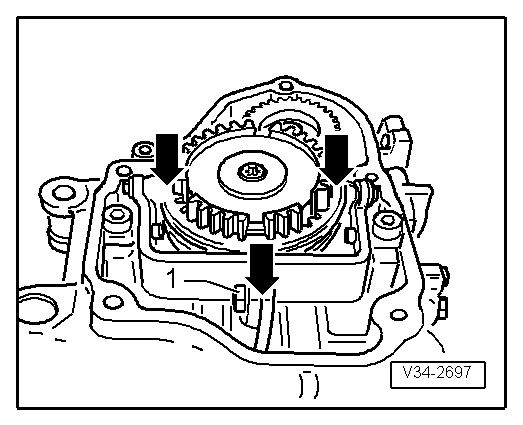
–  Install the gasket and gearbox casing cover.
–  Tighten the bolts to secure the gearbox casing cover to a torque of 10 Nm.
  V34-2697
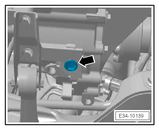
–  Screw the drain plug -arrow-and tighten to a torque of 25 Nm.
–  Fill the gearbox with oil → Booklet601, noting the quantity filled → Chapter
–  Fit left wheel housing moulding → Bodywork, exterior fitting work; Rep. gr. 66
–  Fit the centre soundproofing → Bodywork, exterior fitting work; Rep. gr.50
–  Install the left front wheel.
  E34-10139

Reverse gear shaft: Disassembling and assembling > < Input shaft: Disassembling and assembling