Power transmissionInput shaft: Disassembling and assembling
| Input shaft: Disassembling and assembling |
| Consult the equivalence table for tools and equipment according to applicability among Seat / VW / Audi / Skoda → Chapter. |
|
|
|
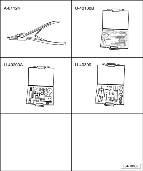
| Special tools and workshop equipment required |
| t
| Extractor kit -U 40100B -, see equivalent → Anchor |
| Remove the outer track of the conical roller bearing |
| –
| First remove guide bush → Chapter, Clutch release assembly: repairs. |
|
|

|
| Install the outer track of the conical roller bearing |
|
|

|
| Removing the roller bearing |
|
|

|
| Install the roller bearing |
|
|

|
| Remove the 4th gear mesh, roller bearing, thrust washer and bush for needle roller bearing. |
| –
| Install flat base -U 40100/3- on the input shaft under the 4th gear mesh. |
| The gear wheel of the 4th gear is removed together with the conical roller bearing, the end washer and the needle bearing sleeve. |
|
|

|
| Removing the gear pinion for 3rd gear |
| –
| Remove the securing ring with pliers -A 81124- before removing the gear pinion for 3rd gear. |
|
|

|
| Fit the gear pinion of 3rd gear |
| The gear pinion collar must be facing the gear pinion for the 4th gear. |
|
|

|
| Fit the gear pinion of 4th gear |
| The gear pinion collar must be facing the gear pinion for the 3rd gear. |
|
|

|
| Install the roller bearing |
| –
| Install flat base -U 40100/3- below the 2nd gear mesh, and position adapter -U 40200/19- side A oriented towards roller bearing. |
|
|

|
| Fit the attack washer and the bush for gear needle roller bearing |
| –
| Install flat base -U 40100/3- below the 2nd gear mesh, and position adapter -U 40300/8- side B oriented towards roller bearing socket. |
|
|

|
| Remove the outer track of the conical roller bearing |
|
|

|
| Install the outer track of the conical roller bearing |

Note | If the input shaft has been adjusted, the shim must be fitted before assembling the outer track of the roller bearing |
|
|

|
| Install synchromesh assembly of 5th gear |
| Install synchromesh assembly of 5th gear in the following way: |
| –
| Place the sliding sleeve -2- on the synchromesh hub -3- so that the base strips align -A- in order to house the locking keys -4- of both components, and the teeth terminating in the end of the sliding sleeve are situated in the same direction as the most pronounced lug -B- of the locking keys. |
| –
| Install the locking keys -4- and secure them with the springs -1- separating them 120º below the steps of the locking keys. |
|
|

|
| Install springs in synchromesh assembly of 5th gear |
| –
| Check that the teeth terminating in end -A- of the sliding sleeve are located in the same direction with the most pronounced lug -B- of the axle box. |
| –
| Check that locking pins are correctly installed → Fig.. |
| –
| Position the springs separating them 120º, under steps -C- of the locking keys. The angled ends of the springs -arrows- must be outside the locking keys. |
|
|

|
01 Transmission
The same page in:
Leon Mk2.