| t
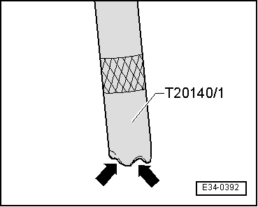
| Do not over-expand safety rings. |
| t
| Retaining rings must locate properly in grooves. |
| t
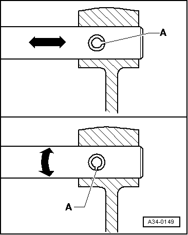
| Renew spring pins. Fitting position: the groove -A- is positioned lengthwise to the flow of the pressure -arrow-. |
| t
| Loosen bolts and nuts in reverse of tightening sequence. |
| t
| The bolts and nuts to be used to secure covers and casings must be released and tightened diagonally in stages when no tightening order is specified. |
| t
| Replace bolts and self-locking nuts. |
| t
| Specified torques given are for unlubricated nuts, bolts and screws. |
| t
| Threaded holes where there had been self-locking bolts or bolts with thread fixing agent must first be cleaned (for example, with a threading male). If this is not done, the bolts may break when removed again. |
| t
| In all bolted unions, ensure that supporting surfaces and bolts and nuts are only waxed after installation, if this is necessary. |
| t
| Check pitch of thread, to ensure correct thread chaser is used to clean threads and to ensure the threads are not damaged. |
| t
| Install new roller bearings as supplied (without additional oiling). |
| t
| All bearings (apart from roller bearings) of the gearbox must be fitted lubricated with gear oil. |
| t
| Before fitting interior rings of roller bearings, first heat them to 100 ºC approx. Use the electric blower -SAT 1416-. When installing, they must be pressed in to their limit, without leaving axial play or rebound. |
| t
| The temperature can be measured with the digital thermometer -SAT 4002-. |
| t
| Do not confuse the outside and inside rings of the bearing with the rings from other bearings of the same size. |
| t
| Roller bearings fitted into one same shaft must be replaced together, using products of the same manufacturer. |
| t
| Position gear needle roller bearings with the stamped side (thicker plate) towards the mandrel to be fitted. |
| t
| Measure shims at several points with a micrometer. The existence of different tolerances allows the necessary shim thickness to be selected exactly. |
| t
| Check for burrs and damages. Install only perfect shims. |
| t
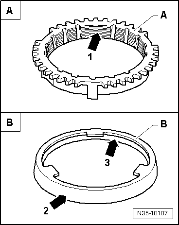
| Do not interchange! When reusing synchro-rings, always fit to the same selector gear. |
| t
| Check for wear and renew if necessary. |
|
|
|
 WARNING
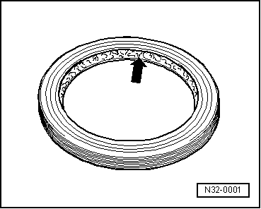
 Note
Note