seat Workshop Repair Guides

SEAT Workshop Service and Repair Manuals

Gear drive mechanism: repairing > < Gearbox: Dismantling and assembling
Removing
Removing
–  With the ignition switched off, disconnect the battery earth strap.
  Note!
For vehicles fitted with a coded radio, first check the anti-theft code.
–  Remove air filter: → Rep. Gr.24.
–  Press the clutch to the floor several times.
–  Remove the clutch cable from its location on the clutch release lever: Clutch cables with automatic adjustment → Chapter. Clutch cables without automatic adjustment (steering wheel on the right) → Chapter.
   
–  Disconnect the speedometer sender connector -arrow-.
–  Separate the connector with its bracket, from the cluch housing, at the front.
  V34-2538
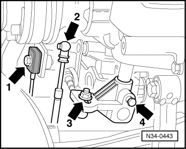
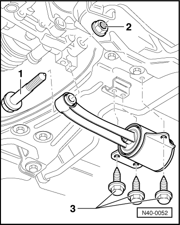
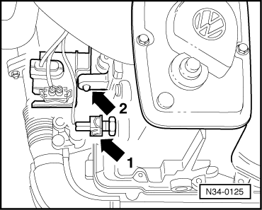
–  Unbolt the cable and connector bracket from the gearbox -arrow 2-.
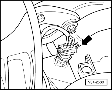
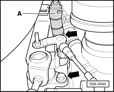
–  Separate the reversing light connector -arrow 1-.
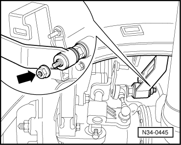
–  Unbolt the earth cable from the engine to gearbox bolt.
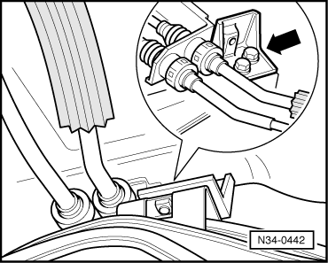
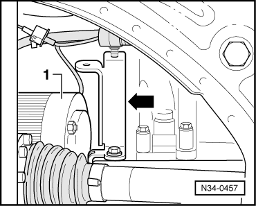
–  Remove the cable guide from its gearbox fittings.
–  Remove the upper bolts that secure the engine to the gearbox.
–  Remove sump insulation tray, if fitted: → Bodywork Repairs, installation work, exterior; Rep. Gr.50.
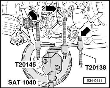
–  Remove the drive shafts from the gearbox flanges using the correct spanner from tool Kit XZN -U-40020-.
–  Turn steering towards the left completely.
–  Hold the left-hand driveshaft as high as possible and secure it conveniently, taking care not to damage it.
  N34-0125
–  Remove the counter-hold bracket -arrow- from the subframe.
Vehicles with a diesel engine
–  Remove front exhaust pipe: → Rep. Gr.26.
Continued for all vehicles
  N34-0442
–  Remove the counter-support bolt -arrow- and remove the support.
  N34-0445
–  Remove the control cable -arrow 1- and the selector cable -arrow 2-.
–  Unbolt the selector rod with ball joint from the control finger -arrow 3-.
–  Remove the control finger by loosening the bolt -arrow 4-.
  N34-0443
–  Unbolt the selector rod bracket from the gearbox -arrows-.
A - long socket spanner, e/c 13 mm
–  Remove the flywheel cover plate.
  N34-0444
–  Remove the pendulum support, unbolting -1- and -3- and removing nut -2-.
  N40-0052
–  Removing the cable guide bracket -arrow-.
–  Removing the starter motor -1-: → Electrical system; Rep. Gr.27.
  Note!
In diesel-powered vehicles, the starter motor is located at the front of the gearbox casing.
  N34-0457
–  Fit the bracket -U-30025E-.
–  Pretension the engine assembly slightly by means of the support device spindles.
  Note!
Remove all cable brackets, cables and hoses that could interfere with the fitting of the support tool.
  E34-0409
–  Remove the two hexagon bolts -arrows- from the left gearbox console.
–  Carefully tilt the engine to the left. To do this, lower the left-hand spindle of support device -U-30025E- slightly.
–  Fit tool -T20145- together with tool -T20138- onto jack -SAT 1040-.
  N34-0124
–  Place the jack below the gearbox, and secure tool -T20138- to the gearbox, in such a way that it is secure -arrows-.
–  Remove the lower gearbox bolts.
–  Release the gearbox from the dowel pegs and lower it carefully.
  E34-0411

Gear drive mechanism: repairing > < Gearbox: Dismantling and assembling