
Leon Mk1
| Assembly chart |
 Note!
Note!| t | Disconnect the negative terminal of the battery. |
| t | In vehicles fitted with a coded radio, first consult the anti-theft code. |
| t | Lubricate all joints and sliding surfaces with molybdenum sulphide (MoS2)-based lubricating grease. |
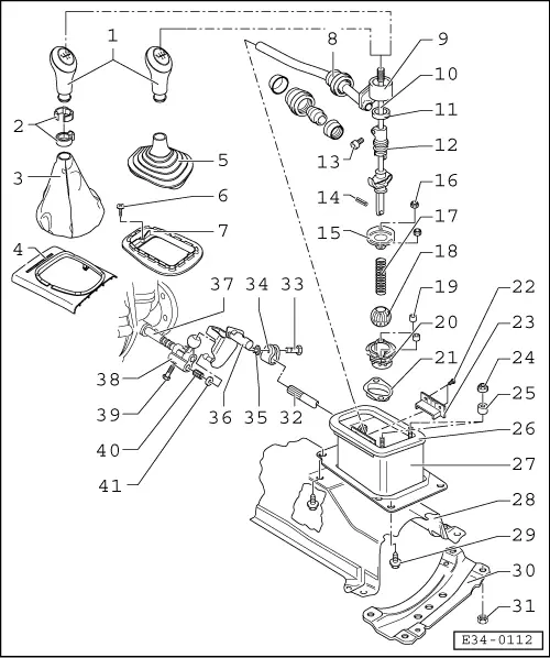
| 1 - | Gear lever knob |
| q | Assign according to the Replacement Parts Microfiche. |
| 2 - | Clamp and retaining bush |
| q | For securing the knob and the hood to the gear lever. |
| q | Assembly → Chapter |
| 3 - | Hood |
| q | Join to the gear lever knob before assembling. |
| q | Assembling → Chapter |
| 4 - | Mounting |
| q | Dismount from the centre console → Body - interior assembly work; Rep. Gr.68. |
| 5 - | Rubber hood |
| q | Join to the gear lever knob before assembling → Chapter |
| 6 - | Screw |
| 7 - | Mounting |
| 8 - | Bearing sleeve of the drag link |
| q | When assembling, make sure that the two parts do not separate. |
| 9 - | Drag link |
| q | Remove from the casing along with the gear lever → Fig. |
| q | Install after fitting the gear lever. |
| 10 - | Gear lever |
| q | Before dismounting, remove the adjusting cam → Fig. |
| q | Before fitting the gear lever, insert the following: locking disc → Item, spring → Item, ball → Item and secure them with the pin → Item |
| 11 - | Plastic ring |
| q | Attach over the slot of the adjusting cam. |
| 12 - | Adjusting cam |
| q | Fit on the gear lever after having fitted this. |
| 13 - | Securing screw for the adjusting cam, 2 Nm |
| 14 - | Pin |
| q | Dismounting and assembly → Fig. |
| 15 - | Locking disc |
| q | Assembly position → Fig. |
| 16 - | Hexagonal nut |
| q | Self-locking. |
| q | Always replace. |
| 17 - | Spring |
| 18 - | Ball |
| 19 - | Separator bush |
| 20 - | Ball mounting |
| 21 - | Joint |
| q | For the ball mounting. |
| 22 - | Rivet |
| q | For securing the lug |
| 23 - | Lug |
| 24 - | Plastic nut |
| q | For securing the centre console to the gear selector box casing. |
| 25 - | Separator bush |
| 26 - | Gasket |
| q | Bond to the casing of the gear selector box. |
| 27 - | Gear selector box casing |
| q | Dismounting and assembly → Chapter |
| 28 - | Thermal protecting plate |
| 29 - | Hexagonal screw, 20 Nm |
| q | For securing the casing of the gear selector box to the body. |
| 30 - | Bridge-piece |
| 31 - | Hexagonal nut, 20 Nm |
| q | Self-locking. |
| q | Always replace |
| 32 - | Drag link |
| 33 - | Screw |
| 34 - | Clamp |
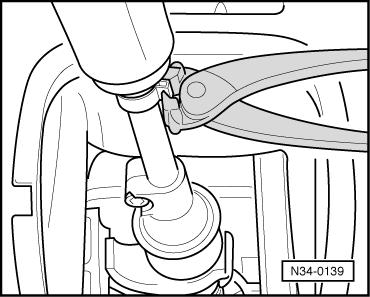
| q | Loosen the screw → Item to dismount the drag link |
| 35 - | Hexagonal nut, 20 Nm |
| q | Put on after fitting the gear change. |
| 36 - | Elbow toe |
| 37 - | Connector shaft |
| 38 - | Connector finger |
| q | Clean the threaded hole. |
| 39 - | Hexagonal screw, 20 Nm |
| q | Always replace. |
| 40 - | Bush |
| 41 - | Joint |
|
|
|
|
|
|
|
|
|
|
|