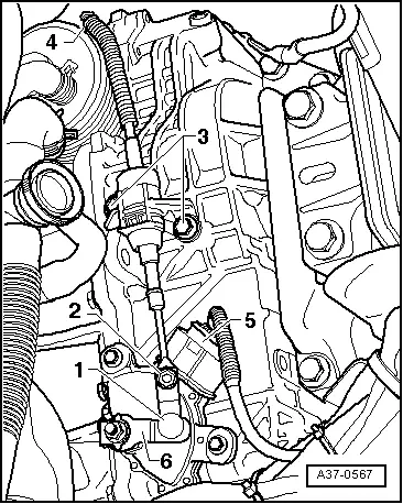
seat Workshop Repair Guides

SEAT Workshop Service and Repair Manuals

Multi-function switchF125 : adjustment > < Multi-function switchF125 : removing, fitting and adjustment
Multi-function switchF125 : removing and fitting
Multi-function switch -F125 -: removing and fitting
Removal:
  Note
t  Cleaning norms when working in the gearbox → Chapter.
t  General repair instructions. → Chapter
  Note
All cable clamps that become loose or cut when removing must be re-installed in the same place when installing.
–  Place the selector lever in position „N“.
–  Switch off ignition.
–  Remove engine cover → Booklet101.
   
–  Remove the air filter body, breather hose and air duct hoses → Rep. gr.24 and → Rep. gr.23 .
–  Release the selector lever control cable -1- from the selection shaft rod -6-, using, for example a size 10 fixed spanner ensuring, at the same time not to kink the cable.
  Note
Do not unscrew the bolt -2-.
–  Disconnect the connector -5- on the multi-function switch.
  A37-0567
–  Remove the rod from the selection shaft -1-.
  A37-0575
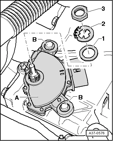
–  Using a screwdriver, fold back the hooks of the securing ring -2-.
  Note
The securing ring must be replaced if, when bending, one or more hooks break.
–  Remove the nut -3- along with the washers -2- and -1-.
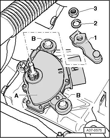
–  Unscrew the two bolts -B- and extract the multi-function switch -A- upwards passing the length of the selection shaft.
Installation
Installation is carried out in the reverse order; noting the following:
–  Insert the Multi-function switch -F125- in the selection lever.
–  Screw in the attachment bolts -B- for the multi-function switch by hand.
–  Fit the washers -1-, -2- and the nut -3- on the selection shaft.
  A37-0576
–  Secure the nut by folding the hooks of the securing ring -2-.
  Note
The securing ring must be replaced if, when bending, one or more hooks break.
–  Adjust the Multi-function switch -F125- → Chapter.
  A37-0576
–  Fit the rod of the selection shaft -1-.
  Note
The gear box must remain in position „N“; place the gear lever in position „N“ if necessary.
  A37-0575
–  Connect the connector -5- on the multi-function switch.
–  Insert the selector lever control cable -1- on the selection shaft lever -6- taking care not to bend the selector lever control cable.
  Note
Under certain circumstances, it is necessary to position the selection shaft rod in the correct position to be able to push in the selector lever control cable.
–  Check the selector lever cable adjustment → Chapter.
Tightening torques
  A37-0567
ComponentNm
Multi-function switch -F125- to the selection shaft7
Selection shaft rod to the selection shaft12,5


Multi-function switchF125 : adjustment > < Multi-function switchF125 : removing, fitting and adjustment