seat Workshop Repair Guides

SEAT Workshop Service and Repair Manuals

Gear selection mechanism: as necessary > < Gear mechanism: repairing
Removing
Removing
–  Disonnect the battery earth strap.
  Note
Observe the measures to be adopted when disconnecting the battery → Rep. Gr.27.
  Note
For vehicles fitted with a coded radio, first check the anti-theft code
–  Remove engine cover. → Booklet2
–  Remove air filter housing; gasoline engines → Rep. Gr.24 and diesel engines → Rep. Gr.23.
–  Remove the battery and the battery support: → Electrical system; Rep. Gr.27
  Note
Note the relay lever shaft bushes.
   
–  Remove the securing washer -A- and the gear engagement cable from the relay/connection lever.
–  Extract the securing washer -arrow 1- from the relay lever and remove the assembly with the cable -B- from the selector lever cover.
–  Remove gear selector/engagement rod; to do this, the nut must be unscrewed -arrow 2-.
  E34-0310
–  Unbolt the cable support from gearbox -arrows-.
–  Position the cable assembly and lever so that they do not interfere with the subsequent operations.
  E34-0299
–  Unplug connector from speed sender -arrow-.
  E34-0319
–  Unplug connector from the starter motor -1-.
–  Extract the connector for reverse lights arrow -2-.
–  Rotate the upper mounting bolt from the starter. -3-.
–  Disconnect the hook -4- all the way, and remove the hose.
  E34-0311
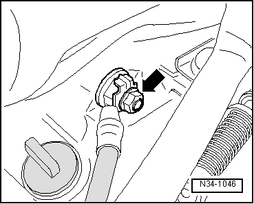
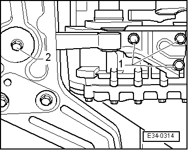
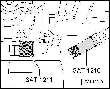
–  Seal off the pressure conduits of the clutch circuit using the clutch circuit seal (male) -SAT 1211- on the side of the clutch slave cylinder, and using the clutch circuit seal (female) -SAT 1210- on the side of the clutch master cylinder.
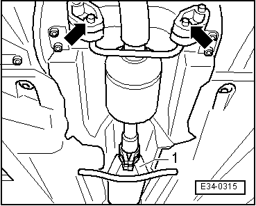
  WARNING
Do not depress clutch pedal after removing slave cylinder.
  Note
t  Brake fluid is toxic. It should not come into contact with the paintwork due to its corrosive effects.
t  
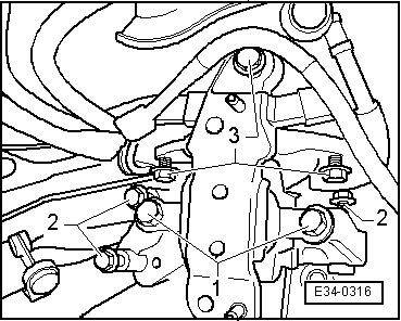
When handling the brake fluid hoses, place a large protective cover or cloth with no loose threads under the clutch slave cylinder adaptor.
  E34-10010
–  Remove the earth cable from the upper gearbox to engine attachment bolt.
–  Remove the upper bolts joining the engine and the gearbox.
  N34-1046
–  Separate the hoses and cables that may be in the area of the engine where the rings that grip the support -U 30025E- go.
  Note
t  Ensure that the pipe connections and the cables in the area where the engine is suspended do not suffer any damage while fitting the hooks of the support equipment.
t  When placing support -U 30025E-, ensure that the support struts remain well seated in the profile of the wing and the bar of the tool. Find the centre of the mechanical unit without damaging the bodywork.
–  Put some force on the drive train using the spindles.
–  Turn the wheels left.
–  Remove front left-hand wheel.
–  Remove left-hand side wheel well.
  Note
There is no need to empty the coolant during the following operation.
  E34-0313
–  Bring the lock carrier into service position → Rep. -Gr. 50; Body - Installation outside: Lock carrier
–  Remove the thermal protection plate from the right hand side drive shaft.
–  Disconnect the drive shafts from the flanged axles and secure them as high as possible so that they do not impede the following operations.
Before removing the bolts, mark the fitting positions with respect to the strut.
  E10-0082
–  Extract the bolts -1- on the left hand side securing the ball joint to the strut.
–  Separate the two ends of the link rod -2- from the stabilizer -arrow- and rotate the two ends towards the bodywork.
  E34-0286
–  Remove the pendulum support on the gearbox side extracting the bolts -1-.
–  Remove the pendulum support on the bridge side, extracting the bolt -2-. Always replace torque: 40 Nm + 90°.
–  Unscrew lower starter motor fixing bolt and remove starter motor.
  E34-0314
–  Loosen the bolts of the double clamp -1- and release the suspension elements -arrows-.
  E34-0315
–  Unscrew gear holder. Turn the mounting screws-1- from the console.
–  Partially lower the drive train to unhook the gearbox attachment bracket and extract the bolts -2-.
–  Extract the bolts -3- securing the bracket to the bodywork, and separate the bracket assembly.
  E34-0316
–  Remove the small protection plate -A- for the engine flywheel.
–  Extract the conical securing bolt from the right hand side flanged shaft; screw in two bolts onto the flange and lock the shaft with the help of an assembly lever.
  N34-1121
–  Affix the gear on the gearbox bracket -T20138C- to the support -T20145- and to the Engine-/ gear jack -SAT 1040-
–  Extract the gearbox/engine lower securing bolts, disengage gearbox from guide sleeves.
–  Regulate the base -T20145- so that gearbox moves without force on the rigid drive shaft, at the same time separating gearbox from engine.
  Note
Do not damage power steering lines and coolant lines when lowering gearbox.
  E34-10175

Gear selection mechanism: as necessary > < Gear mechanism: repairing