seat Workshop Repair Guides

SEAT Workshop Service and Repair Manuals

Gear selection mechanism (gearbox side) removing and fitting > < Input shaft, secondary shaft, differential gear and gearbox change prongs. Assembly overview
Gearbox housing, operation mechanism, input shaft, secondary shaft, differential gear and gearbox forks: Removing and installing
   
Gearbox housing, operation mechanism, input shaft, secondary shaft, differential gear and gearbox forks: Removing and installing
Consult the equivalence table for tools and equipment according to applicability among Seat / VW / Audi / Skoda → Chapter.
Special tools and workshop equipment required
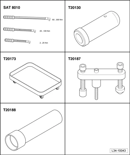
t  Torque wrench kit -SAT 8010-, see equivalent → Anchor
t  Tappet -T20130-, see equivalent → Anchor
t  Collecting tray -T20173-, see equivalent → Anchor
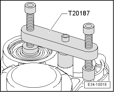
t  Counterhold -T20187-, see equivalent → Anchor
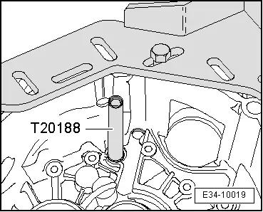
t  Tappet -T20188-, see equivalent → Anchor
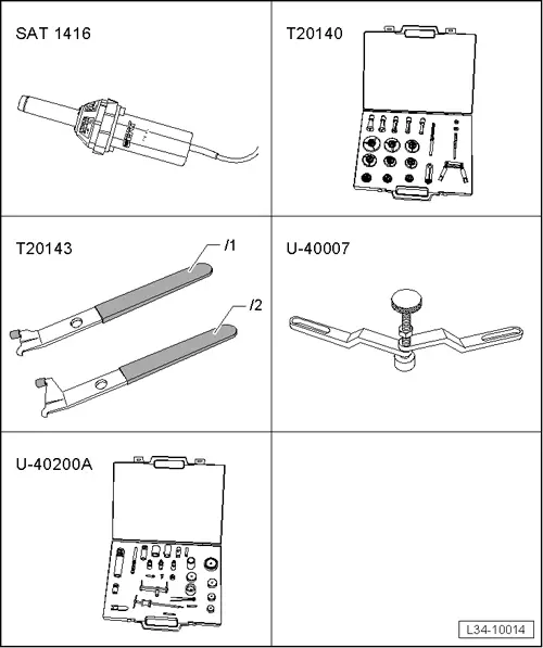
   
t  Hot air blower -SAT 1416-, see equivalent → Anchor
t  Digital thermometer -SAT 4002-, see equivalent → Anchor
t  Extractor kit -T20140-, see equivalent → Anchor
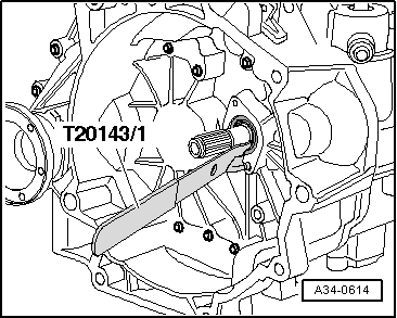
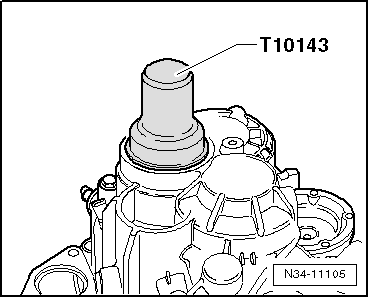
t  Extraction lever -T20143-, see equivalent → Anchor
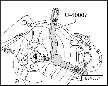
t  Retention tool -U 40007-, see equivalent → Anchor
t  Kit (case) -U 40200A-, see equivalent → Anchor

   
t  Puller -T10143-, see equivalent → Anchor
t  Removing → Anchor
t  Installing → Anchor
Removing
–  Remove gearbox → Chapter.
–  Attach the gearbox to the stand → Chapter.
–  Rotate the gearbox on the assembly frame so that the oil plug bolt is downwards.
–  Fit tray -T20173- beneath gearbox.
–  Drain gearbox oil.
  W00-10214
–  Screw out bolts -arrows-.
–  Remove the slave cylinder with the collar -A-.
  A30-0012
–  Extract input shaft seal by levering with extractor kit -T20143-.
  Note
Do not damage contact surface for input shaft seal.
  A34-0614
–  Fill space between sealing lip and dustcap -arrow-, halfway, with sealing grease → Spare parts catalogue.
–  Fit seal flush with installation tool -T20130-.
  N32-0001
–  Place the gearbox mechanism shaft in the neutral position; to do this release the locking pin -arrow-.
–  Unscrew the locking bolt -2-.
–  Extract the bolts -3-.
–  Extract the selector shaft -4- from the gearbox housing.
  Note
-Disregard item 1. 1-.
–  Remove the flanged shaft and insert shaft.
  N34-10024
–  Unscrew the bolts -B- securing the gearbox housing from the clutch housing.
  Note
One of the bolts -arrow- is outside the joint flange. This is fitted with a washer.
–  Pierce the rubber seal cover for the centre using a screwdriver.
  N34-0997
–  Remove the circlip -A- for the sealing cover of the input shaft.
  N34-11100
–  Remove the rubber seal cover from the gearbox using the extractor kit -T20140-.
  E34-10007
–  Detach circlip -C- from grooved ball bearing on input shaft as follows:
–  Support one of the securing ring ends using a screwdriver -A-.
–  Release the other end of the securing ring from the ball bearing groove -arrow- using a second screwdriver as a lever -B-.
–  Continue to undo the securing ring with the screwdriver -B-.
  E34-10013
–  Unscrew bolts -A-.
–  Heat the gearbox housing at the input shaft ball bearing allotment using the hot air blower -SAT 1416- for about 10 minutes until reaching a temperature of about 100 ºC.
–  The temperature can be measured with the digital thermometer -SAT 4002-.
  E34-0159
–  Secure the retention tool -U 40007- for the input shaft to the gearbox housing.
  E34-0004
–  Remove the gearbox casing from the clutch housing -arrow- using the pressure tool -T20187-.
  Note
If necessary, apply an assembly lever carefully to the edges of the gearbox housing to undo it, changing from one side to another without causing damage to the sealing surfaces.
  Note
  E34-10018
To remove the shafts from the clutch housing, a second mechanic is required.
–  Lift the differential gear -1- a little with the left hand.
–  With your right hand, lift 1st - 4th gear output shaft together with selector rods -2--arrow A-.
–  At the same time, the second mechanic must remove the primary, inverter and secondary shaft of the 5th / 6th gears -3-, along with the control rods, out of the clutch housing -arrow B-.
  Note
In case of doubt, the differential drive may rest on the clutch housing after lifting the shafts.
–  Release the input shaft oil seal → Chapter.
Installing
  N34-10029
–  Insert input shaft -1- and the output shaft for 5th / 6th gears and reverse gear -2- together with selector rod -3-, selector fork -4- and reverse shaft -5-.
  N34-10030
The reverse gear prong -1- is mounted on the shaft -2- behind the selection shaft of the of the 5th and 6th gear -3- prong.
  Note
To fit the shafts in the clutch housing, a second mechanic is required.
  N34-11437
–  Install the differential -1-.
–  Use the right hand to hold the secondary shaft for the 1st to 4th gears -3- along with the control rods -4-, as shown in the illustration.
–  Lift the differential gear a little with the left hand.
–  At the same time the second mechanic must lift the input shaft and output shaft for 5th, 6th and reverse gear -2- slightly, together with the reverse shaft.
–  Now insert the secondary shaft for the 1st to 4th gears in the -direction of the arrow-.
l  The input shaft, secondary shaft and crown teeth should all be engaged.
–  Using the help of the second mechanic, press the shafts and the differential drive into their seats.
  N34-10031
–  Secure the retention tool -U 40007- for the input shaft to the gearbox housing.
  Note
For clarity, the clutch housing appears rotated 180 º.
–  Screw the centre screw of the -U-40007-retaining tool until the drive shaft partially contact the tool.
  E34-0004
The groove ball bearing of the input shaft can only be installed in the gearbox casing in one position
The ball bearing and its mount have a flattened location.
l  When flattened locations -A- and -B- are present, washers must not be mounted on the top nor on the bottom of the ball bearing.
l  The flattened area -A- of the ball bearing must correspond with the flattening of the mount -B- that is in the gearbox casing for this purpose.
–  Mark the flattened area in colour.
–  Extend the marking up to the top side of the ball bearing and the bearing housing in the gearbox casing (see the following Fig.).
–  Using the hot air blower -SAT 1416-, heat the gearbox casing, in the area of the input shaft groove ball bearing mount for approx. 10 minutes until a temperature of about 100 ºC.
  Note
t  Heating is necessary to ensure that grooved ball bearing is not damaged when installing gearbox housing.
t  Apply the sealing compound equally on the surface of the clutch housing to be sealed → Spare parts catalogue.
  N34-11101
t  Align the marking of the ball bearing -A- to the gearbox casing -B- and mount the gearbox casing above this.
  N34-11102
–  Fit the gearbox housing and tighten the new screws -A-, -B- and -C- with the specified tightening torque.
Allocation of bolts:
A - Bolt with washer
B - Bolt without washer
C - Bolt with washer
–  Fit the circlip for the grooved ball bearing of the input shaft.
–  Extract the counterhold -U 40007-.
  N34-10565
–  If the insertion sleeve for the selection shaft was removed it must be fitted using the mandril -T20188- to the limit of the tool with the gearbox housing fitted.
–  Rotate the gearbox on the assembly frame so that the opening for the selection shaft is upwards.
  Note
For clarity, the seal plug is removed.
  E34-10019
–  Insert the selection shaft -1- into the lower allotment -2- and onto the prongs -3-.
  N34-10035
–  Press the selection rod -1- against the insertion sleeve -2-, -arrow-, and lift it downwards using the finger -3-, by the prongs, to the limit.
l  While doing this, the selector lever mechanism cover -4- should remain parallel to the surface where the gearbox housing is bolted.
l  The selection shaft should be easily moved upwards and downwards (selection movement).
  Note
If the selector lever mechanism cover is inclined relative to the bolted surface, this means that the selection shaft is not inserted in the lower allotment.
  N34-10036
–  Tighten the bolts -3- for the selector lever mechanism cover -4-.
–  Screw in the lock bolt -2-; to do this, the lock pin -arrow- must be unscrewed.
–  Screw in the switch for the reversing light -1-.
–  Fit the flanged shaft and insert shaft.
–  Drive in the input shaft oil seal → Chapter.
–  Fit the clutch slave cylinder with the release collar.
–  Successively select all gears several times.
  N34-10024
–  Insert the sealing cover using the pressure tool -T10143- as far as possible in the gearbox housing.
  N34-11105
–  Secure the sealing cover with the new circlip -A- (when fitted).
–  Install gearbox → Chapter.
  N34-11100

Gear selection mechanism (gearbox side) removing and fitting > < Input shaft, secondary shaft, differential gear and gearbox change prongs. Assembly overview