| t
| Do not over-expand safety rings. |
| t
| The securing rings must be perfectly seated in their groove. |
| t
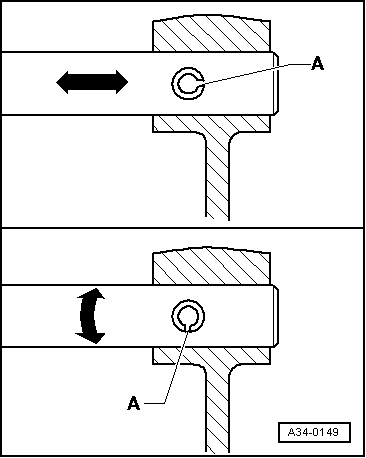
| Replace split pins. Installation position: the groove -A- is positioned lengthwise to the flow of the pressure -arrow-. |
| t
| Loosen bolts and nuts in reverse of tightening sequence. |
| t
| The bolts and nuts to be used to secure covers and casings must be released and tightened diagonally in stages when no tightening order is specified. |
| t
| Always replace self-locking nuts and bolts. |
| t
| The torque settings refer to non-oiled nuts and bolts. |
| t
| Threaded holes where there had been self-locking bolts or bolts with thread fixing agent must first be cleaned (for example, with a threading male). If this is not done, the bolts may break when removed again. |
| t
| In all bolted unions, ensure that supporting surfaces and bolts and nuts are only waxed after installation, if this is necessary. |
| t
| Install new roller bearings as supplied (without additional oiling). |
| t
| All bearings (apart from roller bearings) of the gearbox must be fitted lubricated with gear oil. |
| t
| Before fitting interior rings of roller bearings, first heat them to 100 ºC approx. Use the electric blower -SAT 1416-. When installing, they must be pressed in to their limit, without leaving axial play or rebound. |
| t
| The temperature can be measured with the digital thermometer -SAT 4002-. |
| t
| Do not confuse the outside and inside rings of the bearing with the rings from other bearings of the same size. |
| t
| Roller bearings fitted into one same shaft must be replaced together, using products of the same manufacturer. |
| t
| Position gear needle roller bearings with the stamped side (thicker plate) towards the mandrel to be fitted. |
| t
| Check shim settings at various points, using a micrometer. The existence of different tolerances allows the necessary shim thickness to be selected exactly. |
| t
| Check for burrs and damages. Install only perfect shims. |
| t
| Must not be swapped. Do not mix up synchroniser rings from different gears. |
| t
| Check for wear and replace if necessary. |
| t
| Fit them lubricated with gear oil. |
| t
| Before fitting pinions, they must be cleaned and heated to 100 ºC approx. Use the electric blower -SAT 1416-. |
| t
| The temperature can be measured with the digital thermometer -SAT 4002-. |
| t
| Check whether, after fitting, the mobile pinions of 1st ª to 6thª gear have slight axial play and move easily. |
| t
| When removing the gearbox, the clutch slave cylinder must be extracted without opening the piping system. |
| t
| If the clutch slave cylinder is removed together with the hydraulic pipe, do not press the clutch pedal. Otherwise, the slave cylinder piston will be expelled. |
| t
| Do not incline the pressure disk; loosen slightly in each passage and diagonally, the installation is done in the same way. |
| t
| To reduce the unpleasant smells of a burnt clutch, the clutch bell-housing must be thoroughly cleaned, along with the flywheel and engine at the side facing the clutch. |
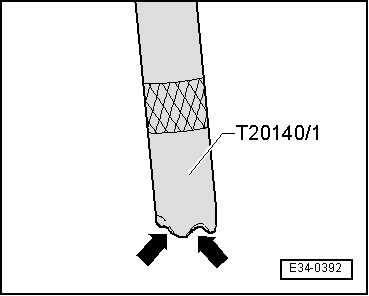
| Extraction of the outer roller bearing rings and the bearing bushes using the kit -T20140- |
| l
| Remove the outer rings of the conical roller bearings or the bearing bushes as follows: |
| –
| Measure (if possible) the internal diameter of the external ring of the roller bearing or the bearing bush. |
| –
| Select the appropriate clamp from the kit -T20140- noting the following: |
| l
| If the diameter measured is less than 30 mm: |
| –
| Fit the valve tappet for small clips /10 and the appropriate clip for internal diameters. |
| l
| If the diameter measured is greater than 30 mm: |
| –
| Fit the valve tappet /28 with the clip /29 and the appropriate grips for internal diameters. |
| –
| Screw nut /5 and washer onto the valve tappet. |
| –
| Place the tool on the outer ring of the roller bearing or the bearing bush and fit the threaded legs so that they are firmly secured. |
|
|
|
 WARNING
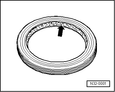
 Note
Note