
Leon Mk1
|
| Special tools and workshop equipment required |
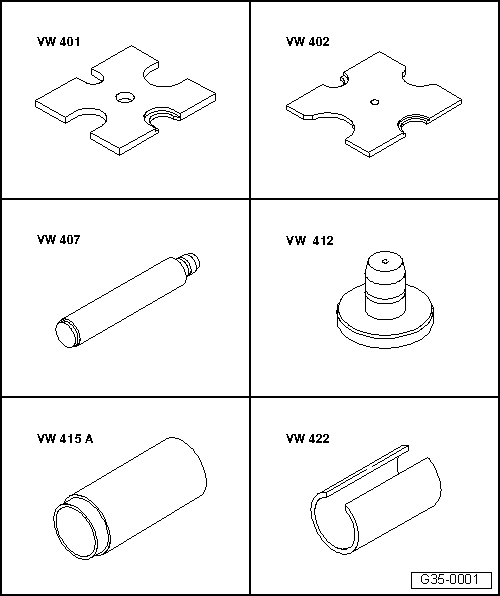
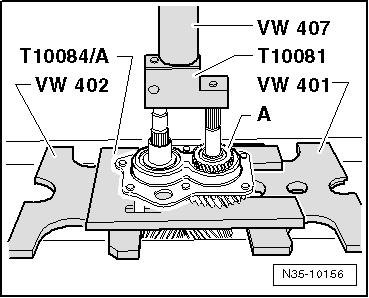
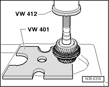
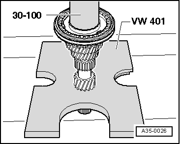
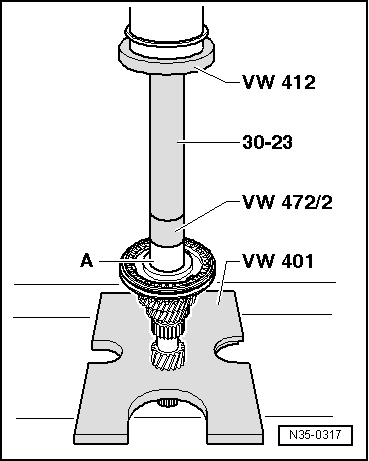
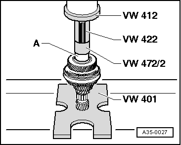
| t | Pressure plate -VW 401-, see equivalent → Anchor |
| t | Pressure plate -VW 402-, see equivalent → Anchor |
| t | Terminal crimper -VW 407-, see equivalent → Anchor |
| t | Terminal crimper -VW 412-, see equivalent → Anchor |
| t | Tube element -VW 415 A- |
| t | Tube element -VW 422- |
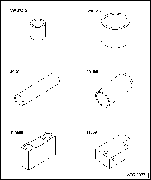
| t | Spacer bush -VW 472/2- |
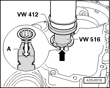
| t | Pipe section -VW 516-, see equivalency → Anchor |
| t | Locking plate -30-23- |
| t | Press tool -30-100- |
| t | pressure tool -T10080- |
| t | pressure tool -T10081- |
|
|
|
|
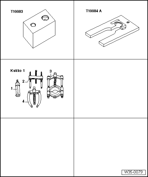
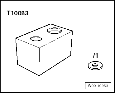
| t | Base for fitting -T10083- |
| t | Tightening plate -T10084 A- |
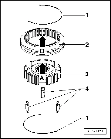
| t | -1-Interior extractor -Kukko 21/5- |
| t | -4-Support bracket -Kukko 22/2- |
|
|
|
|
|
|
|
|
|
|
|
|
|
|
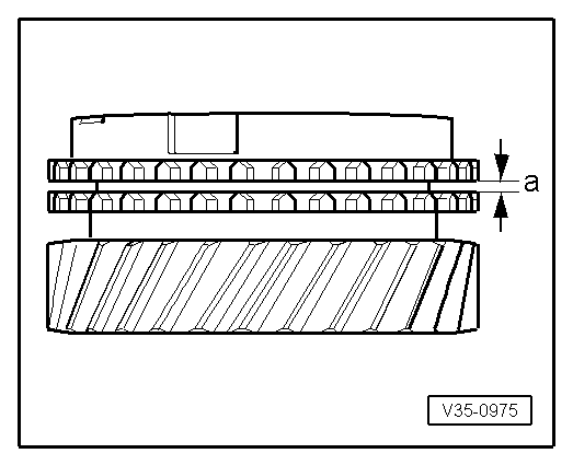
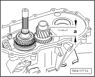
| Gap -a- | Installation dimension | Wear limit |
| 3., 4., 5. and 6th gear | 1.1 ... 1.7 mm | 0.5 mm |
|
|
|
|
|
|
 Note
Note
|
|
| Measured value (mm) | Retaining ring thickness (mm) | Axial play (mm) |
| 0,05 … 0,14 | 2,0 | 0,05 … 0,15 |
| 0,15 … 0,24 | 2,1 | 0,05 … 0,15 |
| 0,25 … 0,34 | 2,2 | 0,05 … 0,15 |
| 0,35 … 0,44 | 2,3 | 0,05 … 0,15 |
| 0,45 … 0,51 | 2,4 | 0,05 … 0,10 |
Note |
|
|
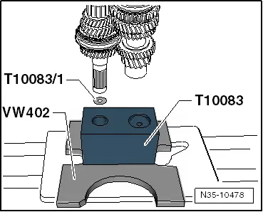
| Dimension -a- = 30.6 mm | |
| Insert shim -T10083/1- ⇒ next figure. |
|
|
|
|
 WARNING
|
|
|
|
|
|