
Leon Mk1
|
| Special tools and workshop equipment required |
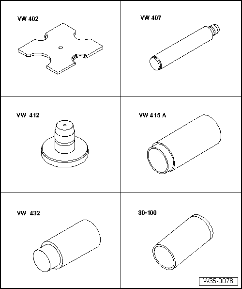
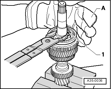
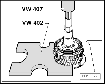
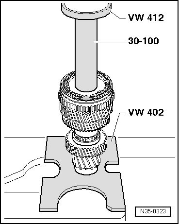
| t | Pressure plate -VW 402-, see equivalent → Anchor |
| t | Terminal crimper -VW 407-, see equivalent → Anchor |
| t | Tube element -VW 415 A- |
| t | pressure tool -VW 432- |
| t | Press tool -30-100- |
|
|
|
|
|
|
|
|
 WARNING
|
|
|
|
|
|
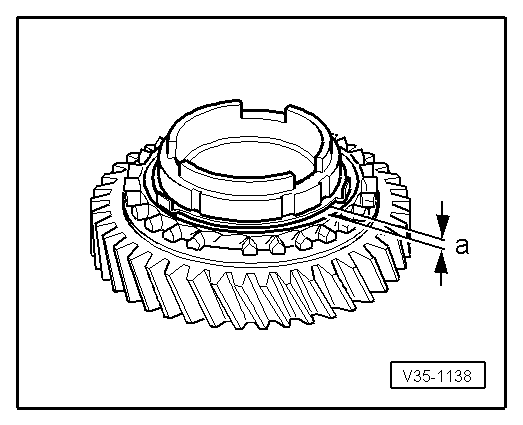
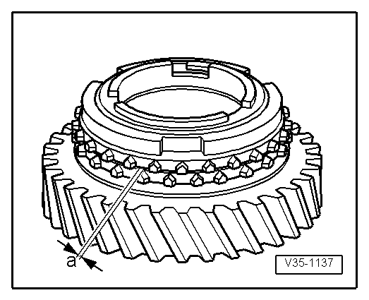
| Gap „a“ | Installation dimension | Wear limit |
| 1st and 2nd gears | 0.75...1.25 mm | 0.3 mm |
|
|
| Gap „a“ | Installation dimension | Wear limit |
| 1st and 2nd gears | 1.2 ... 1.8 mm | 0.5 mm |
|
|
|
|
|
|
|
|
|
|
|
|
|
|
|
|