seat Workshop Repair Guides

SEAT Workshop Service and Repair Manuals

Removing and installing ATF cooler > < Position of selector elements
Assembling gearbox
Assembling gearbox
Special tools and workshop equipment required
t  Spacer pins -T10317-
t  Straightedge -T40100-
   
–  Install freewheel.
Use “smallest lug” for orientation. The freewheel fits only in one position.
All the following parts also have a similar “small lug”. The lugs must always be aligned.
For better orientation, the parts will be shown in “cutaway” figures in subsequent steps.
  N37-10235
The installed freewheel looks like this in the “cutaway” gearbox:
The freewheel is secured with a retaining ring.
  N37-10237
–  Install retaining ring.
The open side of the ring faces the selector shaft. The -ends- of the ring absolutely must be installed as shown in this figure.
  N37-10236
–  Insert first outer plate of brake “B1” with “smooth” side upwards.
The underside has a shoulder. This is for the freewheel retaining ring.
Use “smallest lug” for orientation. The outer plates also fit in one position only.
–  Insert first inner plate of “B1”.
–  Install all remaining plates alternately.
Insert last outer plate, “approximately 2.5 mm thick”.
–  “Align” teeth of inner plates.
This will ease the later installation of clutch “K1”.
  N37-10238
–  Insert dished spring -A- with convex side “upwards”.
  N37-10239
The outer edge of the dished spring -A- lies on the last outer plate.
  N37-10240
–  Insert spring seat.
  N37-10241
–  Insert spring.
–  Now examine “B1” piston. There are a “lug” and a hole on the outer circumference.
  Note!
The “B1 piston” must not be inserted while the “valve body” installed.
  N37-10242
–  Insert “B1” piston as shown in the figure.
Carefully guide spindle of assembly tool -3253/3- through spur gear because sleeve on lower end must not be damaged.
  N37-10243
–  Press down piston to stop using assembly tool -T10064/1-, -T10064/6A- and spindle from assembly tool -3253/3-.
–  Fit retaining ring.
  N37-10244
No tool is shown here so that it can be seen how to install the retaining ring.
The open side of the ring faces “opening” to band brake. Here, too, the -ends- of the ring absolutely must be installed as shown in this figure.
  N37-10245
Now check position of piston!
l  The -hole--arrow- in the piston must be visible in the valve body.
–  Remove assembly tool.
  N37-10246
–  Attach needle bearing to clutch “K1” with Vaseline.
The dark side faces the gearbox.
–  Carefully insert clutch “K1”.
  N37-10247
–  Turn clutch “to the left”. This will cause it to slide into the freewheel.
  N37-10249
The clutch is properly installed if the “edges”-A- of the bearing seat and -B- of the clutch are equally high.
  N37-10248
–  Insert needle bearing for annulus.
  N37-10250
–  Attach thrust washer to annulus with Vaseline.
The washer fits only in one position.
  N37-10251
–  Turn annulus “back and forth” while inserting it.
  N37-10252
–  Insert needle bearing for planet carrier.
  N37-10253
–  Attach thrust washer to planet carrier with Vaseline.
–  Turn planet carrier “back and forth” while inserting it.
  N37-10254
–  Insert axial needle bearing for large sun gear.
  N37-10255
–  Install large sun gear.
  N37-10256
–  Attach axial needle bearing to planet carrier with Vaseline.
The dark side faces the planet carrier.
  N37-10257
–  Turn planet carrier “back and forth” while inserting it.
  N37-10258
The planet carrier is correctly installed if the teeth along the circumference are engaged in the clutch cage of “K1”.
  N37-10259
–  Insert axial needle bearing for annulus.
  N37-10260
–  Attach thrust washer in annulus with Vaseline.
The washer fits only in one position.
–  Turn annulus “back and forth” while installing it.
  N37-10261
–  Attach axial needle bearing to annulus with Vaseline.
  N37-10262
–  Install annulus.
  N37-10263
–  Insert first outer plate of brake “B2”.
It is “about 4.2 mm thick”.
The outer plates fit only in one position.
  N37-10264
–  Insert first inner plate of “B1”.
–  Install all further plates alternately. The two outer plates are “about 3 mm thick”.
There are two versions of the last “B2 outer plate”.
I “Later gearboxes” One outer plate “about 7.5 mm thick” is inserted last.
  N37-10265
II “Earlier gearboxes” Two outer plates “about 3.8 mm thick” are inserted last.
–  Install retaining ring.
Before continuing assembly, check air space of “B2”.
Checking air space of 2nd, 4th and 5th gear brake “B2”
  N37-10266
–  Measure and note value at last outer plate of “B2”.
Example: 26.15 mm
–  Press piston of “B2” into cover to stop.
  N37-10287
–  Measure from across two lugs of “B2 piston” to sealing surface of cover and note value.
Example: 25.37 mm
–  Subtract the lesser of the two measurements from the greater.
Example: 26.15 mm - 25.37 mm = 0.78 mm
Specification: 0.60 - 0.90 mm
  N37-10288
–  Attach axial needle bearing in “K2/K3” with Vaseline.
–  Turn “K2/K3”“back and forth” when installing it.
  N37-10267
–  Insert axial needle bearing -A-.
–  Lay thrust washer on bearing (it is stuck in cover).
Before continuing assembly, first check axial play of entire planetary gear set.
Checking axial play of planetary gear set
To check play, measurements must be made. But one must determine where play is before “taking measurements”.
  N37-10268
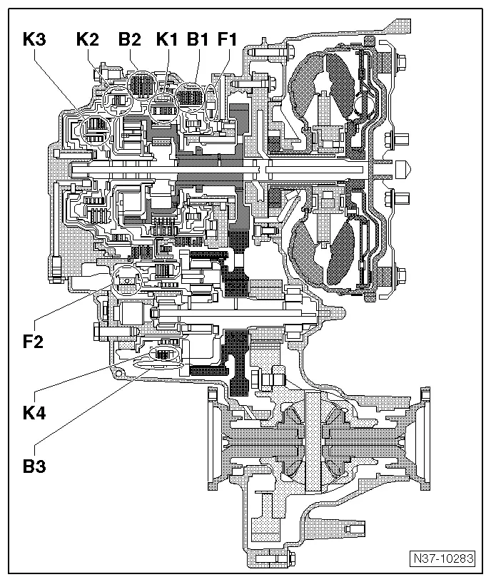
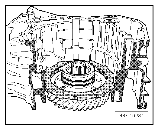
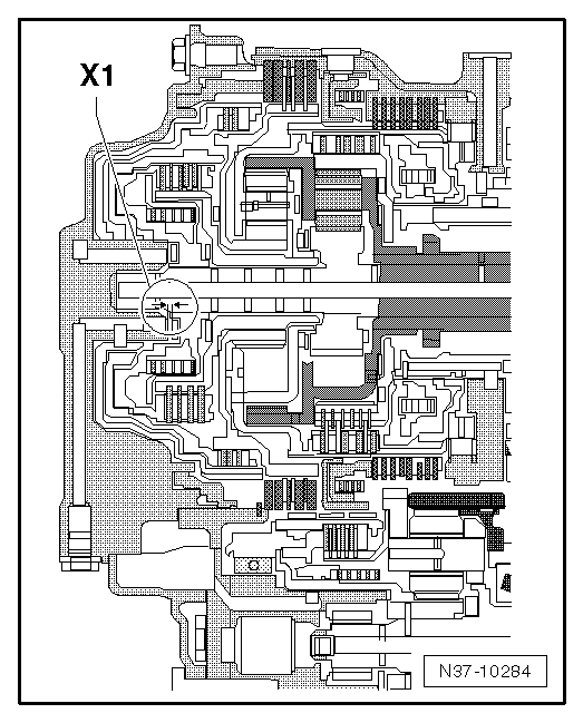
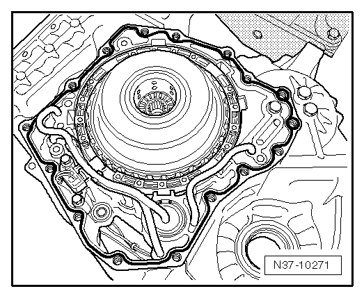
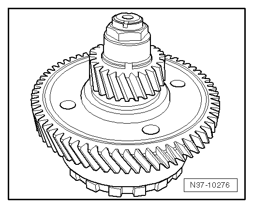
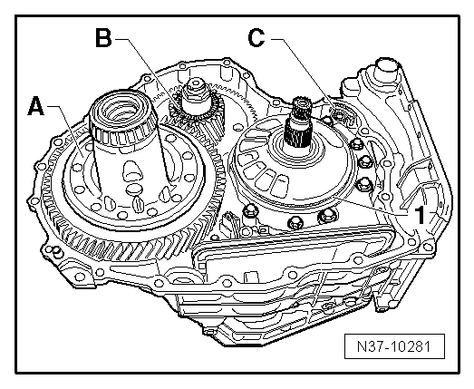
The entire gearbox is shown here.

   
–  Here the location of the first play -x1- to be measured is shown.
Determining x1
Three measurements must now be taken. The goal is to obtain two measured values, “a” and “b”.
Calculating dimension “a”
–  Secure spacer pins -T10317- to cover using nuts.
Hand-tight is sufficient.
  N37-10284
–  Take measurement at “seat” of thrust washer and note value.
Example: 125.30 mm
  N37-10286
–  Take a measurement at contact surface of cover and note value.
Example: 107.75 mm
(This value represents the height of the pins and straightedge of the measuring apparatus. It will be “needed” again later. You can then copy it from your notes. You do not need to repeat the measurement.
–  Subtract the lesser of the two measurements from the greater.
In our example, the calculation looks like this 125.30 mm - 107.75 mm = 17.55 mm = “a”.
–  (Replace the values in the example with your measurements!)
Now “a” has been calculated. Note this value. “a” = ?
Calculating dimension “b”
  N37-10282
–  Tighten spacer pins -T10317- hand-tight in gearbox.
–  Take measurement at thrust washer and note value.
Example: 90.70 mm
Here, too, must one value be subtracted from the other. One of the values (example: 107.75 mm), at the contact surface of the cover, has already been measured.
Example: 107.75 mm - 90.70 mm = 17.05 mm = “b”
–  (Replace the values in the example with your measurements!)
(107.75 mm comes from the first measurement.)
Now “b” has been calculated. Note this value. “b” = ?
Calculating x1
x1 = “a” - “b”
Example: 17.55 mm -17.05 mm = 0.50 mm
  N37-10231
The value must be within the specification.
Specification: 0.25...0.55 mm
The gearbox may be further assembled only if this value has been attained. If this value has not been attained, a mistake has been made and it must first be corrected.
Assembly continuation
–  Remove thrust washer again from “K2” and attach in cover with Vaseline.
  N01-0453
–  Install spring -2-.
The spring fits only in one position.
–  Install gearbox input speed sender -G182--1-.
Next, the ATF lines must be installed. Do not cant lines during installation and push both ends evenly into gearbox housing to “stop ”.
  N37-10269
–  First install ATF lines -1- and -2-.
–  Then install ATF line -3- with line clips -A-.
  N37-10270
–  Insert seal -B- into gearbox housing.
Then clean cover.
–  Clean sealing surfaces with cleaning solution -D 009 401 04-.
  Note!
Sealing surfaces must be absolutely free of oil and grease. Leaks may otherwise result.
The cover may be installed after it is cleaned.
  N37-10268
–  Attach thrust washer in cover with Vaseline.
The cover must be sealed against gearbox with sealant -D 176 404 A2-.
  N37-10289
–  Sealant must be applied in a thin “3 mm wide” bead to gearbox housing as shown in figure.
  N37-10271
Applying a “wider” bead with good intention does not seal “better”, but rather leads to malfunctions.
–  Set gearbox housing cover in place.
  N01-0453
–  First “start” bolts -1- and -2- by hand and tighten down to cover.
This way the rubber rings under bolts -1- will find the optimal seat in cover.
–  “Start” all other bolts by hand and tighten down to cover.
–  Tighten bolts -1- to 35 Nm.
–  Then tighten bolt -2- to 20 Nm.
–  Finally tighten remaining bolts to 20 Nm.
–  Turn gearbox.
–  Install brake band “3”.
  N37-10272
–  Assure proper seating in catch -1- and plunger -2-.
  N37-10273
–  When installing clutch “K4”, raise brake bank slightly with a wire.
–  Insert axial needle bearing -1-.
  N37-10274
–  Install gear -A- with retaining ring “downwards”.
–  Align inner plates of “K4”.
  N37-10275
–  Now pick up planetary gear set III.
  N37-10276
–  Insert it far enough that the spur gears engage.
  N37-10277
–  Turn it “back and forth” until the two spur gears are in the same plane.
The “turning back and forth” thread the plates into the plate carrier.
It is “best” to use a -T-bar- with a 32 mm -socket-.
  N37-10278
–  Install turbine shaft -A-. Turn shaft “back and forth” and push into gearbox to stop.
The shaft is correctly installed if the lower shoulder -arrow- of shaft contacts spur gear.
–  There must be no seal in the groove -1- of the turbine shaft during installation of the ATF pump. Remove it first.
–  Lay gasket -B- for ATF pump on pump flange.
  N37-10279
–  Install ATF pump and strainer and tighten bolts to 20 Nm.
–  If there is still a seal in groove -1- remove it.
  N37-10280
–  Next insert differential cage -A- and then axial needle bearing -B-.
  N37-10281
Two versions of gasket -C-
–  Measure thickness of mounting plate.
Two different thicknesses of gaskets are included in the repair component.
  N37-10291
–  Install gasket -C- having the same thickness as the gasket which was removed.
–  Install new seal -1- for ATF pump.
Then clean torque converter housing.
–  Clean sealing surfaces with cleaning solution -D 009 401 04-.
  Note!
Sealing surfaces must be absolutely free of oil and grease. Leaks may otherwise result.
The torque converter housing may be installed after it is cleaned.
The torque converter housing must be sealed using sealant -D 176 404 A2-.
  N37-10281
–  Apply a “3 mm wide” bead of sealant to gearbox housing as shown in figure.
  N17-0019
Applying a “wider” bead with good intention does not seal “better”, but rather leads to malfunctions.
–  Set torque converter housing in place.
–  Tighten all 21 bolts by hand.
–  Tighten bolts diagonally to 28 Nm.
  N01-0453

Removing and installing ATF cooler > < Position of selector elements