
Leon Mk1
| Electrical and electronic components and their locations |

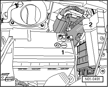
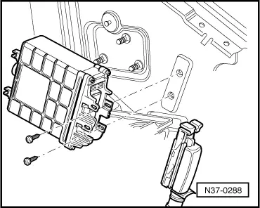
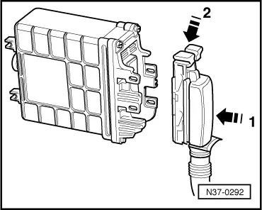
| 1 - | Automatic gearbox control unit -J217- |
| q | Fitting location → Fig.. |
| q | Removing → Fig.. |
| q | Installing → Fig.. |
| q | The control unit transmits and receives data from the data bus. |
| 2 - | Engine control unit |
| q | Location and removing and installing → Fig.. |
| q | The control unit transmits and receives data from the data bus. |
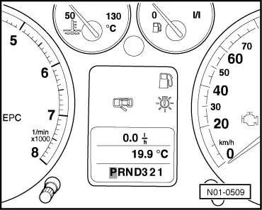
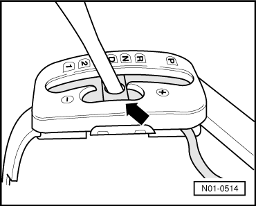
| 3 - | Selector lever position display -Y6- |
| q | Fitting location → Fig.. |
| q | Simultaneous illumination of all selector lever position display segments indicates gearbox emergency running mode. |
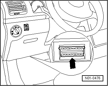
| 4 - | Diagnostic connection |
| q | Fitting location → Fig.. |
| 5 - | Multi-function switch -F125- |
| q | Removing, installing and adjusting → Chapter. |
| q | Can be checked using “guided fault finding” of -VAS 5051-. |
| 6 - | Intermediate shaft speed sender -G265- |
| q | Picks up a signal at gear A (intermediate speed). |
| q | Location: in gearbox. |
| q | Can be checked using “guided fault finding” of -VAS 5051-. |
| q | Removing and installing → Chapter. |
| 7 - | Vehicle speed sender -G68- |
| q | Measures gearbox output shaft speed (vehicle speed). |
| q | Location: in gearbox. |
| q | Can be checked using “guided fault finding” of -VAS 5051-. |
| q | Removing and installing → Chapter. |
| 8 - | Gearbox input speed sender -G182- |
| q | Measures gearbox input shaft speed (turbine shaft). |
| q | Location: in gearbox. |
| q | Can be checked using “guided fault finding” of -VAS 5051-. |
| q | Removing and installing → Chapter. |
| 9 - | Gearbox oil temperature sender -G93- |
| q | Location: in gearbox. |
| q | Can be checked using “guided fault finding” of -VAS 5051-. |
| q | As part, available only with gearbox wiring harness → Electronic parts catalogue “ETKA”. |
| q | Removing and installing → Chapter. |
| 10 - | Selector lever lock solenoid -N110- |
| q | Location and removing and installing → Chapter. |
| q | Can be checked using “guided fault finding” of -VAS 5051-. |
| 11 - | Brake pressure switch -F270- |
| q | Location: switch is located on front wall, in brake line to front right brake calliper. |
| q | Signal can be checked using “guided fault finding” of -VAS 5051-. |
| 12 - | Valve body |
| q | Location: in gearbox. |
| q | Removing and installing → Chapter. |
| q | The solenoid valves -N88-, -N89-, -N90-, -N91-, -N92-, -N93-, -N281-, -N282- and -N283- are attached to the valve body → Chapter. |
| q | The valves can be checked using “guided fault finding” of -VAS 5051-. |
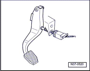
| 13 - | Brake light switch -F- |
| q | Location and removing and installing → Fig.. |
| q | Can be checked using “guided fault finding” of -VAS 5051-. |
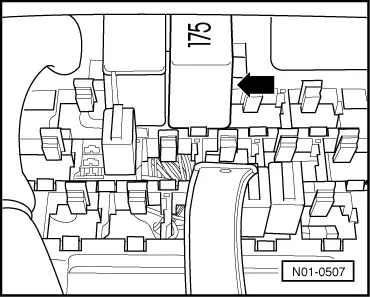
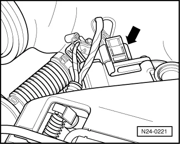
| 14 - | Starter inhibitor and reversing light relay -J226- |
| q | Fitting location → Fig.. |
| 15 - | Kickdown switch -F8- |
| q | Fitting location → Fig.. |
| q | Can be checked using “guided fault finding” of -VAS 5051-. |
| 16 - | Tiptronic switch -F189- |
| q | Removing and installing → Chapter. |
| q | Can be checked using “guided fault finding” of -VAS 5051-. |
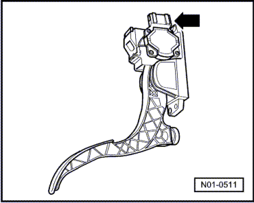
| 17 - | Throttle valve potentiometer -G69- or accelerator pedal position sender -G79- |
| q | → Fig. |
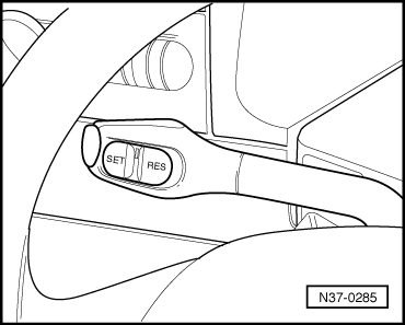
| 18 - | Cruise control system switch -E45- |
| q | Fitting location → Fig.. |
| q | Removing and installing → Electrical system; Rep. Gr.94. |
|
|
|
|
|
|
|
|
|
|
|
|
|
|
|
|
|
|
|
|
|
|
|
|