
Leon Mk1
| Removing gearbox |

| Special tools and workshop equipment required |
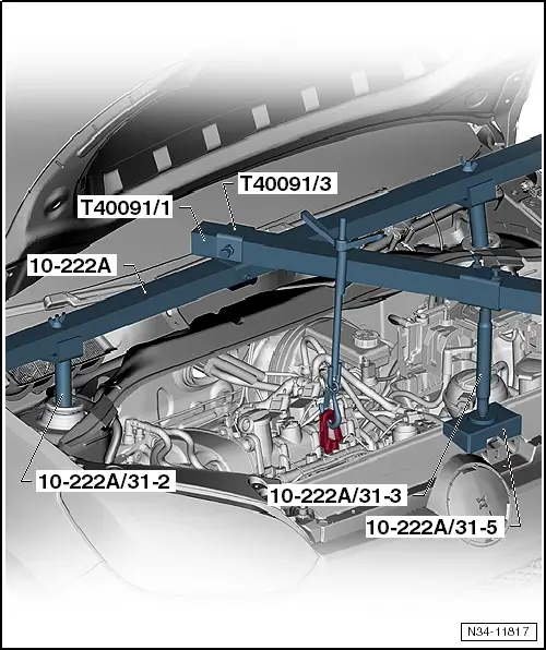
| t | Support bracket -10 - 2 A- |
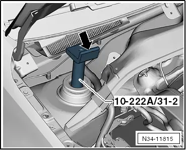
| t | Adapter -10 - 2 A /31-2- |
| t | Support -10 - 2 A /31-3- |
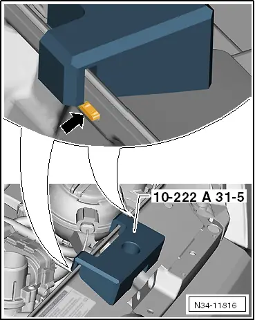
| t | Adapter -10 - 2 A /31-5- |
| t | Square tube -T40091/1- |
| t | Connector -T40091/3- |
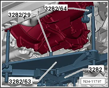
| t | Gearbox support assembly -3282- |
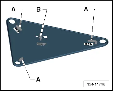
| t | Adjustment plate -3282/63- |
| t | Adapter -3282/64- |
| t | Support elements for gearbox (determine when setting adjustment plate on gearbox support) |
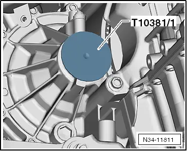
| t | Sealing cap -T10381/1- |

| t | Torque wrench -V.A.G 1331- |
| t | Torque wrench -V.A.G 1332- |
| t | Engine and gearbox jack -V.A.G 1383 A- |
| t | Gearbox lifting tackle -3336- for transporting gearbox |
| t | Grease for clutch plate splines -G 000 100- |
| t | Allocate grease using → Electronic parts catalogue (ETKA). |
|
|
|
|
|
|
|
 Caution
|
|
|
|
|
|
|
|
|
|
|
|
|
|
|
|
|
|
|
|
|
|
|
|
|
|
|
|
|
|
 Note
Note
|
|