seat Workshop Repair Guides

SEAT Workshop Service and Repair Manuals

Gearbox mechanics,operation, construction,diff.|Gearbox > < Gearbox: remove
Gearbox: assembly
Gearbox: assembly
  WARNING
If the input shaft or the gearbox housing have been renewed, you must first re-determine the thickness of the input shaft circlips → Chapter.
t  Assembly overview of the input shaft → Chapter
t  Assembly overview of the secondary shaft → Chapter
  Note
t  Lubricate all needle bearings with gear oil before fitting.
t  
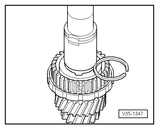
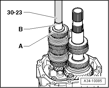
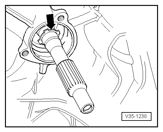
Check synchro-rings for wear → Fig.
t  
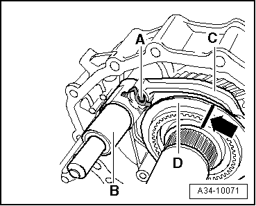
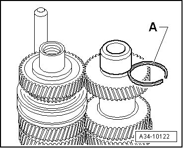
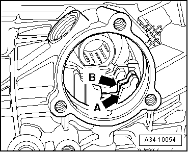
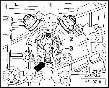
Insert spring in selector gear → Fig.
t  
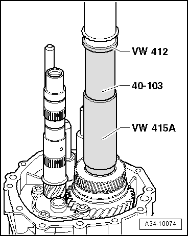
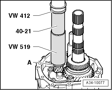
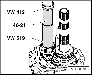
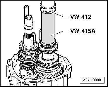
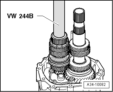
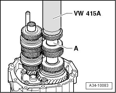
Heat gear wheels, needle bearing inner races and synchronising hubs to 130 °C (max.) before pressing on (wear protective gloves).
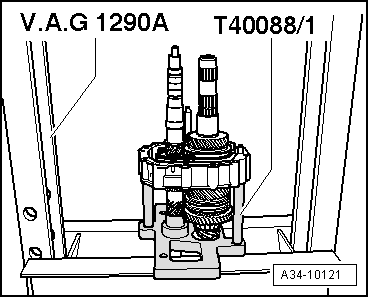
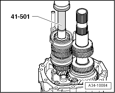
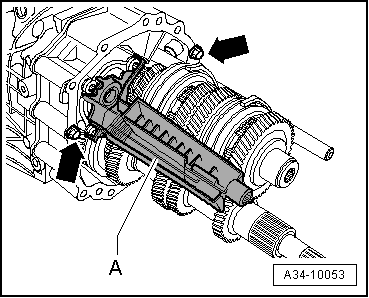
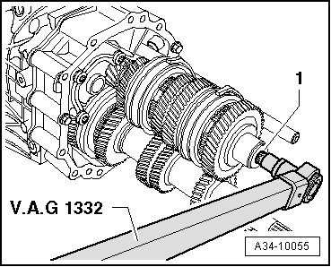
–  Insert output shaft in bearing housing and selector fork for 1st and 2nd gear.
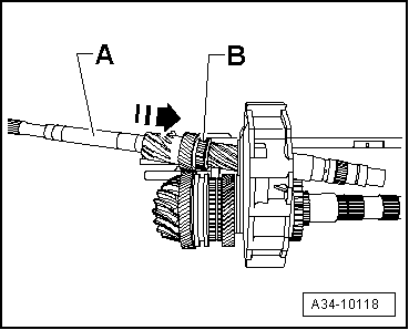
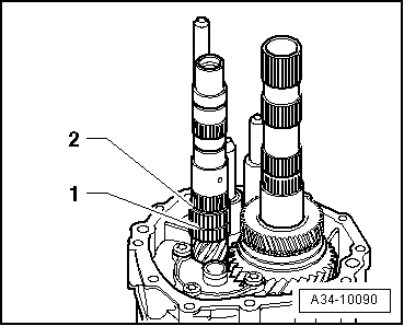
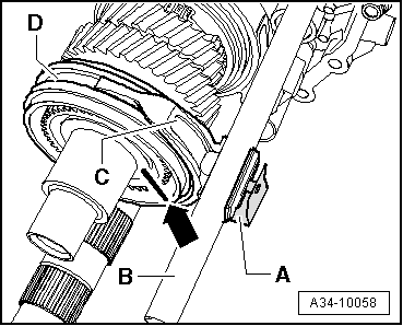
–  Place reverse gear selector gear with needle bearing, spring and synchro-ring onto output shaft.
l  The lugs on synchro-ring should engage into recesses in selector gear.
   
–  Press on reverse gear synchronising hub.
l  Installation position: High inside collar faces 3rd gear wheel.
–  Check axial clearance of reverse selector gear.
  Caution
If the input shaft has been adjusted and, respectively the ring width of the securing rings has been determined, the input shaft must be removed from the bearing housing again before the following assembly step can be carried out.
  A34-10073
–  Now insert input shaft -A- with needle roller bearing -B- into bearing housing in -direction of arrow- at an angle towards the rear.
  A34-10118
–  Install reverse gear wheel and tighten 3 bolts -arrows- for reverse shaft support to 30 Nm.
Exploded view - reverse gear wheel → Fig.
  A34-10120
–  Slide reverse gear selector fork -C- together with locking collar -D- onto selector rod -B- and reverse gear synchronising hub.
l  The markings on locking collar and synchronising hub -arrow- must coincide.
l  The chamfer on the locking collar faces the reverse selector gear.
–  If the bores of selector fork and selector rod coincide, clip in pin with clip -A-.
  A34-10071
–  Place plate -T40088/1- on press table and insert the bearing housing with shafts and selector rods.
  A34-10121
–  Press on 3rd gear wheel.
l  Installation position: Machined side faces reverse gear synchronising hub.
–  Insert circlip for 3rd gear wheel.
  WARNING
When renewing gear wheel or output shaft:
Re-determine thickness of circlip for 3rd gear wheel:
–  Determine the thickest circlip that will just fit and install it. For Part No. refer to → Spare parts catalogue.
The following retaining rings are available:
  A34-10074
Retaining ring thickness (mm)
1,901,982,06
1,942,022,10

   
–  Press on thrust washer -A- for 3rd speed selector gear until limit stop.
  A34-10077
–  Fit needle bearing for 3rd speed selector gear -1- and circlip -2- for 3rd gear needle bearing onto input shaft.
–  Then fit 3rd speed selector gear with spring and synchro-ring.
l  The lugs on synchro-ring should engage into recesses in selector gear.
  A34-10090
–  Press on heated synchronising hub for 3rd and 4th gear
l  Installation position: High inside collar faces 3rd gear wheel.
  A34-10078
–  Insert circlip for synchronising hub for 3rd and 4th gear.
  WARNING
When renewing synchronising hub or input shaft:
Re-determine thickness of circlip for synchronising hub for 3rd and 4th gear:
–  Determine the thickest circlip that will just fit and install it. For Part No. refer to → Spare parts catalogue.
The following retaining rings are available:
  V35-1347
Retaining ring thickness (mm)
1,901,962,02
1,931,992,05

–  Check axial clearance of 3rd speed selector gear.
   
–  Slide selector fork for 3rd and 4th gear -C- together with locking collar -D- onto selector rod -B- and synchronising hub for 3rd and 4th gear.
l  The markings on locking collar and synchronising hub -arrow- must coincide.
–  If the bores of selector fork and selector rod coincide, clip in pin with clip -A-.
  Note
Do not insert the dowel pin with clip for 5th and 6th gear selector fork with a diameter of 6 mm into selector fork for 3rd and 4th gear.
  A34-10063
–  Fit 4th speed selector gear -A- with spring, synchro-ring, needle bearing and thrust washer for 3rd and 4th gear -B-.
–  Press on heated inner race -C- for needle bearing for 5th speed selector gear.
–  Check axial clearance of 4th speed selector gear.
  A34-10081
–  Heat 4th gear wheel and press on.
l  Installation position: High inside collar faces 5th gear wheel.
  A34-10079
–  Heat 5th gear wheel and press on.
l  Installation position: High inside collar faces 4th gear wheel.
  A34-10080
–  Place 5th speed selector gear with spring, synchro-ring and needle bearing onto input shaft.
l  The lugs on synchro-ring should engage into recesses in selector gear.
–  Fit and press on heated synchronising hub for 5th and 6th gear.
–  Check axial clearance of 5th speed selector gear.
  A34-10082
–  Slide selector fork for 5th and 6th gear -C- together with locking collar -D- onto synchronising hub for 5th and 6th gear.
l  The markings on locking collar and synchronising hub -arrow- must coincide.
–  Move selector fork for 5th and 6th gear -C- into selector rod -B-.
–  If the bores of selector fork and selector rod coincide, clip in pin with clip -A-.
  A34-10058
–  Press on heated inner race for needle bearing for 5th speed selector gear.
  A34-10084
–  Fit 6th speed selector gear with spring, synchro-ring, needle bearing and thrust washer for 6th gear -A-.
–  Heat inner race -B- for needle roller bearing and press on.
–  Check axial clearance of 6th speed selector gear.
  A34-10085
–  Fit spacer sleeve -A- onto output shaft.
–  Heat 6th gear wheel and press on.
  A34-10083
Insert circlip -A- for 6th gear wheel.
  WARNING
When renewing gear wheel or output shaft:
Re-determine circlip -A- for 6th gear wheel:
–  Determine the thickest circlip that will just fit and install it. For Part No. refer to → Spare parts catalogue.
The following retaining rings are available:
  A34-10122
Retaining ring thickness (mm)
1,902,022,14
1,932,052,17
1,962,082,20
1,992,11 

–  Take out bearing housing from holding plate -T40088/1 -.
   
–  Secure bearing housing to gearbox housing with two bolts M8 (length approx. 70 mm) -arrows- and washers.
–  Tighten these 2 bolts -arrows- to max. 5 Nm.
  Note
Do not install oil collector -A- at this stage.
  A34-10053
–  Move two selector rods -arrow A- and -arrow B- to lock input shaft by selecting two gears (e.g. reverse gear and 1st gear).
  A34-10054
–  Tighten multi-point socket head bolt -1- for input shaft to 150 Nm.
–  Then remove the complete bearing housing from the gearbox housing.
–  Check if the two dowel sleeves are installed between the gearbox housing and bearing housing.
–  Apply the sealing compound (Allocation → Spare parts catalogue, ETKA) evenly and not too thick onto the dividing plane of the gearbox housing to the bearing housing.
–  Fit bearing housing onto gearbox housing.
  A34-10055
–  Clip oil collector -A- into reverse shaft support.
  Note
Make sure that the bolts -arrows- are removed.
  A34-10053
–  Check if the two dowel sleeves are installed between the bearing housing -B- and gearbox cover -A-.
–  Apply the sealing compound (Allocation → Spare parts catalogue, ETKA) evenly and not too thick onto the dividing plane of the bearing housing to the gearbox housing.
–  Insert securing bolts for gearbox cover -A- and bearing housing -B- to gearbox housing -C-.
  A34-10113
–  Tighten bolts -arrows- to 35 Nm + 90°.
  A34-10112
–  Slide assembly sleeve -01E 311 120--A- to selector shaft -B-.
  Note
To avoid damaging oil seal -C-, oil seal and selector shaft must only be fitted using assembly sleeve -01E 311 120--A-.
–  Move selector rods to neutral.
–  Install complete selector shaft.
t  Installation position: Flat of selector shaft faces downwards
  V34-2598
–  Push selector shaft -2- into gearbox as far as it will go, simultaneously inserting pin -3-.
l  Installation position of cylinder pin -3-: Groove -arrow- on threaded pin points towards selector shaft cover
–  Clean threads of locking bolts -1- with a wire brush. Then insert the screws with locking fluid (Allocation → Spare parts catalogue, ETKA) and tighten to 45 Nm.
  A34-0716
–  Install cover -A- with new O-ring.
–  Clean threads of bolts -arrows- with a wire brush. Then insert the screws with locking fluid (Allocation → Spare parts catalogue, ETKA) and tighten to 24 Nm.
  A34-0715
–  Fit rear circlip -arrow- for input shaft ball bearing.
–  Then push ball bearing onto input shaft.
Installation position:
The sealed side of the ball cage faces the gearbox housing.
  V35-1238
–  Insert the ball bearing:
First screw pin (M8 and M10) -3114/2- into tapped hole for ball head stud.
Slide the thrust plate -T10246/2- onto input shaft.
Now position fitting tool -T10246/1- behind splines for clutch plate. Tighten bolts -A- only slightly. The bolts locate in the recesses in the thrust plate -T10246/2 -.
Press in ball bearing onto the stop by tightening the bolts alternately (1/2 turn at a time).
  A34-10123
–  Now fit front circlip -D- for input shaft ball bearing.
–  Then fit dished spring -C-.
Installation position:
The curved side faces guide sleeve -B-.
–  Fit a shrink hose onto input shaft splines.
–  Fit release bearing guide sleeve -B-.
–  Remove shrink hose.
–  Fit clutch release lever -A- with release bearing.
–  Shift through all gears.
  V30-0375

Gearbox mechanics,operation, construction,diff.|Gearbox > < Gearbox: remove