seat Workshop Repair Guides

SEAT Workshop Service and Repair Manuals

Transporting gearbox > < Gearbox: removing
Gearbox: Install
Gearbox: Install
Installation is carried out in reverse order, noting the following:
–  Use thread tap to remove any remaining locking fluid from all threaded holes which will accommodate self-locking bolts.
–  Always renew self-locking nuts and bolts.
–  Clean the gear teeth of the input shaft and the gear teeth of the hub of used clutch disks, remove any corrosion and only apply a very thin layer of the grease for the clutch-disk spline (Allocation: → Spare Spare parts catalogue). Do not grease guide sleeve.
The clutch plate must slide easily to and fro on the input shaft.
   
–  Check clutch release bearing for wear and renew if necessary.
–  If plastic ring -arrows- has come loose, service release bearing as required → Fig..
  Note
The release bearing must be renewed if the groove worn on the plastic ring is deeper than 0.8 mm.
–  Check, if the adapter sleeves for centring the engine/gearbox unit in the cylinder block are available and install, if necessary.
–  Place the intermediate plate onto the adapter sleeves on the engine flange.
–  Before installing gearbox, tie back electrical lines and holders on one side so that they cannot be pinched between the engine and the gearbox.
  N30-0285
–  On the contact surface between the tappet and the clutch release lever -arrow B-, apply a thin layer of copper grease (allocation →  Spare Spare parts catalogue, ETKA).
–  Raise gearbox far enough to be able to install clutch slave cylinder with bracket for hose/pipe assembly.
–  Guide slave cylinder -1- into opening in gearbox housing, keeping it as straight as possible (without tilting plunger -arrow A-) and insert in recess -arrow B- on clutch release lever -3-.
  Note
If the slave cylinder -1- is inserted at an angle, there is a danger that the plunger -arrow A- will be guided past the clutch release lever -3-.
  Caution
After installing the slave cylinder press the clutch pedal carefully. If you feel an unusually strong point of resistance when depressing the clutch pedal, you must not press it down further. The plunger of the slave cylinder is likely to have been guided past the clutch release lever. The slave cylinder would then be destroyed once pedal force exceeds approx. 300 N.
  A30-0162
–  Secure clutch slave cylinder with new bolt -arrow-.
–  Install gearbox and check whether sufficient space is present for propeller shafts.
  A34-0641
–  Install engine/gearbox securing bolts -arrows A- and -arrows B-.
  A34-0434
–  Install starter → Electrical system; Rep. gr.27.
  N34-0589
–  Slightly lower the gearbox using the engine and gearbox jack -SAT 1040-.
–  If possible, tighten upper engine/gearbox securing bolts -arrows 1- and -arrows 2-.
–  Refasten all lines to gearbox -arrows - C-.
  A34-0704
–  Install clamps -arrows - A - B - to prevent causing noises later.
  A34-10003
–  Install selector shaft lever and tighten nut -arrow-.
  A34-10014
–  Remove pushrod -1-, for this purpose tighten hex. head bolt.
–  Secure connecting rod -2- for selector rod.
  N34-1208
–  Connect connector -arrow- on back-up lamp switch on right side of gearbox.
  A34-0699
–  Slightly raise the gearbox once again using the engine and gearbox jack -SAT 1040-.
–  Attach tunnel cross member to body with new bolts -2- and -3- (tighten hand-tight only).
–  Bolt the gearbox cross member to the gearbox suspension -4- → Chassis, front wheel and four-wheel drive; Rep. gr. 40.
–  Carefully lower the engine and gearbox jack -SAT 1040- and place to the side.
–  Bolt drive shafts -1- to flange shafts → Running gear, front-wheel drive and four-wheel drive; Rep. gr. 40.
  A34-0435
Before tightening subframe, it must be aligned with body using locating pins -3393-.
l  Hole -1-, hole -2- in subframe and hole -3- in aluminium bracket must be in alignment on both sides.
  Note
This alignment can only replace a subsequent wheel alignment if holes -1- and -2- coincided before the repair work was carried out.
–  Bolt on the drive assembly carrier and the gearbox cross member → Chassis, front wheel and four-wheel drive; Rep. gr. 40.
–  Install and adjust the exhaust system free of stress → Rep. gr.26.
  A40-0126
–  Check selector mechanism setting and adjust if necessary → Chapter.
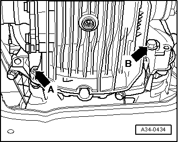
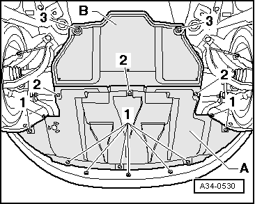
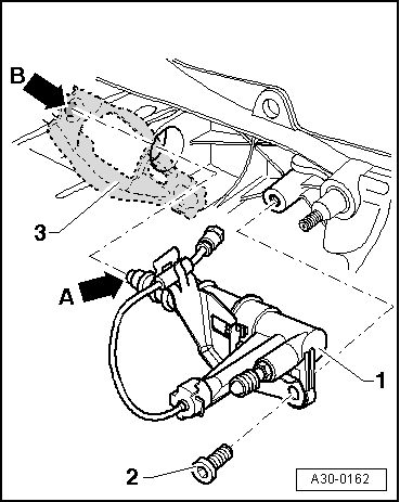
–  Install front soundproofing -A- and, if installed -B-and fasten with quick-type locks -1--2- and -3-.
–  Check oil level in manual gearbox → Chapter.
–  Take all the necessary precautionary measures when connecting the battery → Electrical system; Rep. gr. 27.
–  Perform wheel alignment if required → Running gear, front-wheel drive and four-wheel drive; Rep. gr. 44.
t  
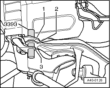
It is not necessary to measure the alignment if the body was fastened with test drifts -3393- before removing and installing the subframe (before tightening the bolt).
t  Wheel alignment must, however, be carried out if the subframe was not located in relation to the body using locating pins -3393- or if it was not possible to fully insert the two pins into the holes.
Tightening torques
  Note
t  The tightening torques listed on this page apply only to lightly greased, oiled, phosphated, or black-finished nuts and bolts.
t  Additional lubricants may be used, for example engine or gear oils, but they should never contain graphite.
t  Use is never to be made of degreased parts.
t  Tolerance for specified torques is ± 15%.
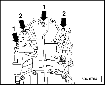
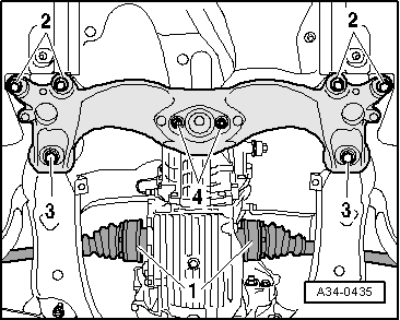
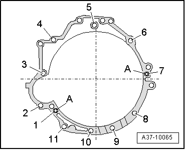
Securing engine to gearbox:
  A34-0530
1.6 litre 75 kW SRE engine
  A37-10065
ItemBolt.Nm
1 → RemarkM12x13065
2, 4M12x7565
3M12x9065
5M12x10065
6M12x11065
7M12x9565
8 → RemarkM10x5045
9, 10, 11M10x4545
Adowel sleeves for centring

1)  With nut
2)  Hammer head bolt with nut
   
1.8 litre 110 kW SRE engine
  A37-10065
ItemBolt.Nm
1 → RemarkM12x11065
2, 4M12x7565
3, 5, 7M12x9065
6M12x11065
8 → RemarkM10x5045
9, 10, 11M10x4545
Adowel sleeves for centring

3)  With nut
4)  Hammer head bolt with nut
   
All other engines
  A37-10065
ItemBolt.Nm
1 → RemarkM12x10565
2, 4M12x8065
3M12x9065
5, 7M12x9565
6M12x10565
8 → RemarkM10x5045
9, 10, 11M10x4545
Adowel sleeves for centring

5)  With nut
6)  Hammer head bolt with nut
   
ComponentNm
Gearbox slave cylinder23 → Remark
Selector shaft lever to gearbox23
Push rod to gearbox40
Connecting rod for selector rod to gearbox23
Gearbox mounting to gearbox 23
Cross member on the gearbox suspension23
Heat shield above drive shaft to gearbox23
Engine mounting to engine support23
Tunnel cross member (front) to body55
Bracket for soundproofing to subframe10

7)  Replace bolt
   

Transporting gearbox > < Gearbox: removing