seat Workshop Repair Guides

SEAT Workshop Service and Repair Manuals

Gearbox: Install > < Gearbox?: removing and fitting
Gearbox: removing
Gearbox: removing
Check the tool and equipment equivalence table according to the applicability between Seat / VW / Audi / Skoda → Chapter
   
Special tools and workshop equipment required
t  Support bracket. -10-222 A-
t  Spacer element -3282/049-, spacer element - 3282/052- and spacer element -3282/048-
t  Hydraulic jack -SAT 1040-, see equivalent → Anchor
t  Torque wrench kit -SAT 8010-, see equivalent → Anchor
t  Gearbox support -T20138C -, see equivalent → Anchor
t  Base -T20145-

   
t  Locating pins -3393-
  W00-0176
t  Flexible-head spanner SW 17 -T20212-
t  Adapter for the hydraulic engine and gearbox jack -SAT 1001/1-
t  Grease for clutch plate splines -G 000 100-
t  Copper grease -Z 381 351 TE-
Operation process
  Note
t  All cable clamps that become loose or cut when removing the gearbox must be re-installed in the same place when installing.
t  Heat insulation sleeves removed during removal of gearbox must be fitted in the same position when installing.
  Caution
Follow steps required when disconnecting battery → Electrical system; Rep. gr.27.
–  With the ignition switched off, disconnect battery earth strap → Electrical system; Rep. gr. 27.
–  Remove the engine cover, depending on the engine → fuel preparation, injection; Rep. gr. 24.
  L26-10003
–  Set up support bracket -10-222 A- with adapters -10-222/3- on wing mounting flanges.
–  Engage spindles on engine lifting eyes as illustrated.
–  Take up weight of engine using spindles.
  A34-10016
–  Loosen bolts/quick release fasteners -1- and -2- and remove front soundproofing -A-.
–  If fitted, loosen quick release fasteners -3- and remove rear noise insulation -B-.
  A34-0530
–  Detach bracket -arrow- for soundproofing.
  Note
  A10-0968
The flexible pipe connection (de-coupling element) on the front exhaust pipe must not be bent more than 10° – otherwise it can be damaged.
–  Separate the exhaust system at the clamp -arrow- and slide the clamp to rear.
Diesel engines
  A26-10015
–  Remove the nuts -arrows- at the front section of the exhaust system.
–  Unscrew exhaust temperature sensor 4 -G648--1- with flexible-head wrench SW 17 -T20212 -. Observe its position for the future re-installation.
  Note
Protect and attach the exhaust gas temperature sensor 4 - G648- accordingly, so that it will not be damaged when removing and installing the transmission.
  A26-10499
–  Remove screw -2- of the bracket and remove the front section of the exhaust system.
Spark-ignition engines
  A26-10120
–  Remove the support tool of the gearbox by unscrewing the bolts -1 and 2-.
Continued for all vehicles
  A26-10120
–  Unscrew the heat shield -1- on the right propeller shaft (if installed).
–  Unbolt drive shafts (left and right) from gearbox flange shafts. Attach accordingly to the body.
  A10-0961
–  Unscrew the three lower engine/gearbox securing bolts -arrow-.
  A34-0433
–  Detach starter from engine/gearbox and secure if necessary → Electrical system; Rep. gr. 27.
  Note
Starter cables do not have to be disconnected.
  N34-0589
–  To be able to remove the manual gear 01X, the gearbox support -T20138C - must be assembled together with the spacer element -3282/049-, thespacer element -3282/052- and the spacer element -3282/048- of the base -T20145- and the hydraulic power lifter adapter -SAT 1001/1-.
  E37-10042
The test pins -3393- must be attached prior to removing the back screws of the assembly bearing.
l  Hole -1-, hole -2- in subframe and hole -3- in aluminium bracket must be in alignment on both sides.
  Note
This alignment can only replace a subsequent wheel alignment if holes -1- and -2- coincided before the repair work was carried out.
  A40-0126
–  First remove bolts -1- and then bolts -2-.
  A34-10147
–  Remove the nuts -arrows- and remove the den gearbox cross member.
–  Slightly lower the gearbox using the engine and gearbox jack -SAT 1040-.
  A37-0448
–  Unplug electrical connector -arrow- for reversing light switch - F4- and move electrical wire clear.
  A34-0666
–  Unscrew connecting rod -2- for selector rod.
–  Unscrew push rod -1- by using an 8 mm hexagon key when unscrewing bolt.
  N34-1208
–  Unscrew nut -arrow- and detach gearbox selector lever from selector shaft.
  A34-10014
–  Remove upper engine/gearbox securing bolts -arrows 1- and -arrows 2-. Please note that retaining brackets for wires/lines and coolant pipe may be secured on bolts -arrows 2- (important for installation).
–  If fitted, remove retaining clips/cable ties together with Lambda probe wiring from gearbox.
  A34-0704
–  Remove remaining engine/gearbox securing bolts -arrow A- and -arrow B-.
–  Disengage the gearbox from the centring sleeve and lower carefully using the engine and gearbox jack -SAT 1040- until the slave cylinder can be accessed.
  Note
  A34-0434
Please verify that the electrical lines that are flange-mounted to the gearbox are not damaged when lowering the gearbox.
–  Remove the clamps -arrows A - B -. Then re-attach so that no noises can be caused.
  Note
When lowering gearbox, ensure hydraulic line to clutch slave cylinder is not damaged.
  A34-10003
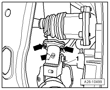
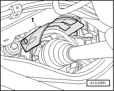
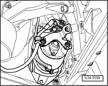
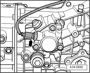
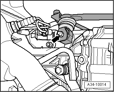
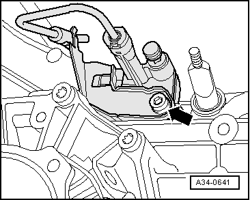
–  Detach clutch slave cylinder from gearbox -arrow- and secure with wire; do not open pipe/hose system.
  Caution
Do not press on the clutch pedal following the removal of the slave cylinder. The slave cylinder would then be destroyed once pedal force exceeds approx. 300 N.
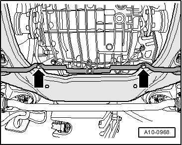
–  Completely lower the gearbox using the engine and gearbox jack -SAT 1040-.
  Note
When lowering gearbox, make sure there is sufficient clearance from drive shafts.
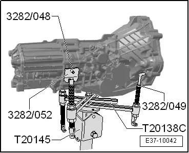
–  Before carrying out assembly work, secure gearbox to assembly stand, using engine and gearbox support -VW 540- → Chapter.
  A34-0641
–  If you will be installing a new gearbox instead of the one removed, the gearbox mounting has to be transferred to the new gearbox -arrows-.
  A34-0703

Gearbox: Install > < Gearbox?: removing and fitting