Leon Mk1
| Drive shaft (drive pinion): Assembly overview |
 Note
Note| t | Refer to technical data → Chapter when installing new gear wheels or the final drive gear set. |
| t | Lubricate all needle bearings on output shaft with gear oil before installing. |
| t | Adjustment work is required when renewing the parts marked with 1). Adjustment overview → Chapter. |
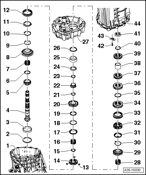
| 1 - | Gearbox housing 1) |
| q | Repairing → Chapter |
| 2 - | Shim „S3“ |
| q | Adjustment overview → Chapter |
| 3 - | Tapered roller bearing outer race 1) |
| q | Remove → Fig. |
| q | Pressing in → Fig. and → Fig. |
| 4 - | Drive shaft (drive pinion) 1) |
| q | Is mated with crown wheel, always renew together as a set |
| q | Adjusting pinion shaft and crown wheel → Chapter |
| 5 - | Tapered roller bearing inner race 1) |
| q | breaks when removing |
| q | replace |
| q | Driving out → Fig. |
| q | Driving in → Fig. |
| 6 - | Circlip |
| q | Re-determine thickness if tapered roller bearing is renewed → Fig. |
| 7 - | Needle bearing |
| q | For 1st gear |
| 8 - | 1st speed selector gear |
| q | Check axial clearance after installing using feeler gauge → Fig. (0.20 ... 0.50 mm) |
| 9 - | Inner ring for 1st gear |
| q | Installation position → Fig. |
| q | Check for wear → Fig. |
| q | Renew if scored |
| 10 - | Intermediate ring for 1st gear |
| q | Installation position → Fig. |
| q | Check for wear → Fig. |
| 11 - | Synchro-ring for 1st gear |
| q | Installation position → Fig. |
| q | Check for wear → Fig. |
| q | Renew if scored |
| 12 - | Locking collar, 1st and 2nd gear |
| q | Mark position in relation to synchronising hub prior to removing |
| q | Assembling the mobile element/synchroniser body → Fig. |
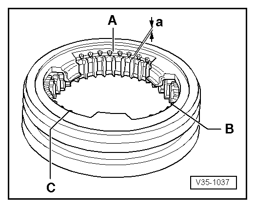
| 13 - | Thrust blocks |
| q | Installing locking pieces (3x) → Fig. |
| 14 - | Synchronising hub for 1st and 2nd gear |
| q | Installation position: High inside collar faces 2nd gear wheel. |
| q | Driving out → Fig. |
| q | Driving in → Fig. |
| q | Assembling the mobile element/synchroniser body → Fig. |
| 15 - | Circlip |
| q | Mark |
| q | Installation position → Fig., -item 1- |
| q | Re-determine thickness when renewing 1st and 2nd gear synchronising hub or pinion shaft → Fig. |
| 16 - | Needle bearing |
| q | For 2nd gear |
| 17 - | Synchroniser ring for 2nd gear |
| q | Installation position → Fig. |
| q | Check for wear → Fig. |
| q | Renew if scored |
| 18 - | Intermediate ring for 2nd gear |
| q | Installation position → Fig. |
| q | Check for wear → Fig. |
| 19 - | Inner ring of 2nd gear |
| q | Installation position → Fig. |
| q | Check for wear → Fig. |
| q | Renew if scored |
| 20 - | Synchromeshed gear for 2nd gear |
| q | Check axial clearance after installing using feeler gauge → Fig. (0.20 ... 0.50 mm) |
| 21 - | Circlip |
| q | Mark |
| q | Installation position → Fig., -item 2- |
| 22 - | Tapered roller bearing inner race 1) |
| q | Driving out → Fig. |
| q | Driving in → Fig. |
| 23 - | Circlip |
| q | Mark |
| q | Installation position → Fig., -item 3- |
| 24 - | Thrust washer |
| q | For reverse gear shaft |
| q | Driving out → Fig. |
| q | Driving in → Fig. |
| 25 - | Tapered roller bearing outer race 1) |
| q | Remove → Fig. |
| q | Driving in → Fig. |
| 26 - | Shim „S4“ |
| q | Adjustment overview → Chapter |
| 27 - | Bearing housing 1) |
| 28 - | Needle bearing |
| q | For reverse gear shaft |
| 29 - | Reverse gear mobile pinion |
| q | Check axial clearance after installing using feeler gauge (0.20 ... 0.50 mm) |
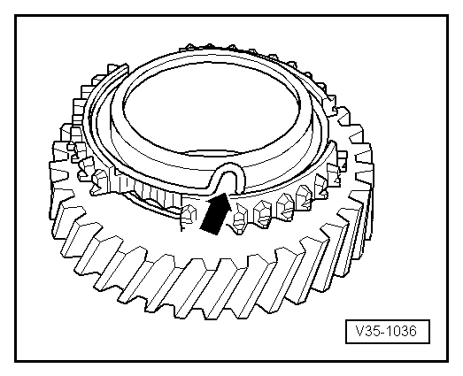
| 30 - | Spring |
| q | Insert into reverse selector gear → Fig. |
| q | Allocation of spring to selector gear → Spare parts catalogue |
| 31 - | Synchro-ring for reverse gear |
| q | Check for wear → Fig. |
| 32 - | Synchronizer body for the reverse gear |
| q | Installation position: High inside collar faces 3rd gear wheel. |
| 33 - | Reverse gear locking collar |
| q | Mark position in relation to synchronising hub prior to removing |
| q | Installation position: Taper faces reverse gear synchro-ring |
| 34 - | 3rd gear wheel |
| q | Installation position: Machined side faces reverse gear synchronising hub |
| 35 - | Circlip |
| q | Mark |
| q | Installation position → Fig., -item 4- |
| q | Re-determine thickness when renewing 3rd gear wheel, reverse gear synchronising hub or pinion shaft → Fig. |
| 36 - | Gear wheel for 4th gear |
| q | Installation position: High inside collar faces 5th gear wheel. |
| 37 - | 5th gear pinion |
| q | Installation position: High inside collar faces 4th gear wheel. |
| 38 - | Spacer bush |
| 39 - | Gear wheel for 6th gear |
| q | Installation position: High inside collar faces spacer sleeve → Item |
| 40 - | Circlip |
| q | Mark |
| q | Installation position → Fig., -item 5- |
| q | Re-determine thickness when renewing gear wheels for 4th ... 6th gear, the spacer sleeve or the pinion shaft → Fig. |
| 41 - | Needle bearing |
| q | Bearing for pinion shaft in gearbox cover |
| q | removing and fitting → Item |
| 42 - | Multi-point socket head bolt, 24 Nm |
| 43 - | Bracket |
| q | Secures needle bearing → Item in gearbox cover |
| 44 - | Gearbox cover |
|
|