
Leon Mk1
 Note
Note
|
 WARNING
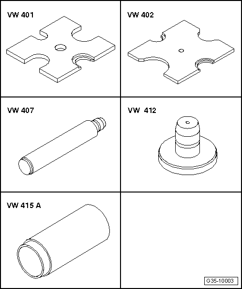
| Special tools and workshop equipment required |
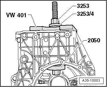
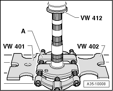
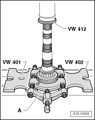
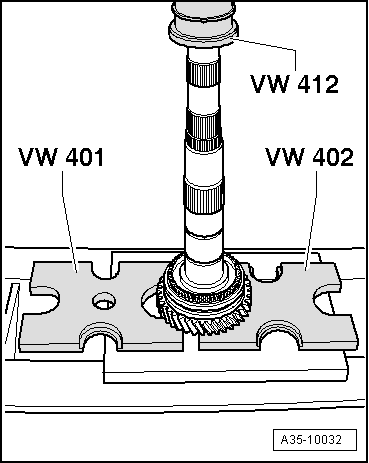
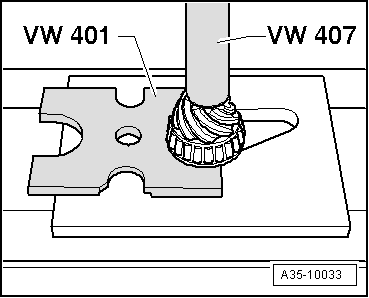
| t | Clutch press -VW 401-, see equivalent → Anchor |
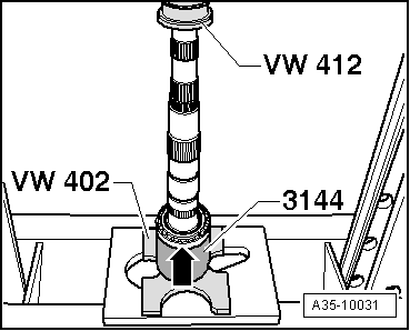
| t | Clutch press -VW 402-, see equivalent → Anchor |
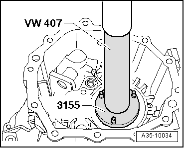
| t | Die -VW 407- |
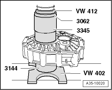
| t | Die -VW 412- |
| t | Tube element -VW 415 A- |
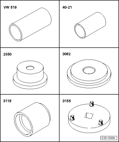
| t | Tube element -VW 519- |
| t | Press tool -40 - 21- |
| t | Thrust blocks -2050- |
| t | Thrust pad -3062- |
| t | Thrust blocks -3118- |
| t | Slotted nut wrench -3155- |
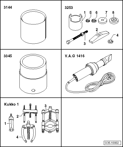
| t | Sleeve -3144- |
| t | Assembly tool -3253- |
| t | Tube for wheel bearing -3345- |
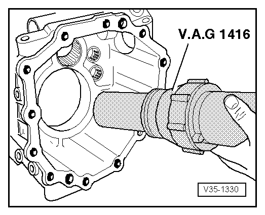
| t | Hot air blower -V.A.G 1416-, see equivalent → Anchor |
| t | -1-Inside extractor -Kukko 21/8-, see equivalent |
| t | -3-Splitter -Kukko 17/2- |
| t | -4-Support bracket -Kukko 22/2-, see equivalent |
| t | Calibre |
|
|
|
|
|
|
|
|
Note
|
|
|
|
 Caution
|
|
|
|
|
|
Note
|
|
|
|
| Retaining ring thickness (mm) | ||
| 2,50 | 2,56 | 2,62 |
| 2,53 | 2,59 | 2,65 |
|
| Retaining ring thickness (mm) | ||
| 1,90 | 2,02 | 2,14 |
| 1,93 | 2,05 | 2,17 |
| 1,96 | 2,08 | |
| 1,99 | 2,11 | |
|
| Retaining ring thickness (mm) | ||
| 3,50 |
|
| Retaining ring thickness (mm) | ||
| 3,50 |
|
| Retaining ring thickness (mm) | ||
| 1,90 | 1,98 | 2,06 |
| 1,94 | 2,02 | 2,10 |
|
| Retaining ring thickness (mm) | ||
| 1,90 | 2,02 | 2,14 |
| 1,93 | 2,05 | 2,17 |
| 1,96 | 2,08 | 2,20 |
| 1,99 | 2,11 | |
|
Note
|
|
|
|
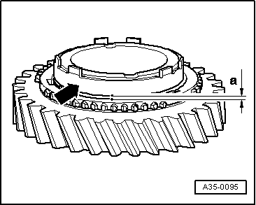
| Gap -a- | As-new installation value | Wear limit |
| 1. Gear - inner ring | 1.2 ... 2.0 mm | 0.6 mm |
|
|
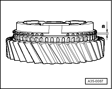
| Gap -a- | As-new installation value | Wear limit |
| 1. and 2nd gear | 1,4 ... 2.0 mm | 0.8 mm |
|
|
|
|
|
|
|
|
|
|
|
|