seat Workshop Repair Guides

SEAT Workshop Service and Repair Manuals

Output shaft for 5th, 6th and reverse gears > < Input shaft
Adjusting output shaft for 1st through 4th gears
   
Adjusting output shaft for 1st through 4th gears
(Determining shim for output shaft)
Special tools and workshop equipment required
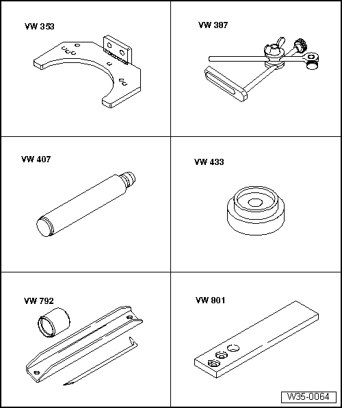
t  Gearbox support -VW 353-
t  Universal dial gauge bracket -VW 387-
t  Press tool -VW 407-
t  Thrust piece -VW 433-
t  Assembly tool -VW 792-
t  Support plate -VW 801-

   
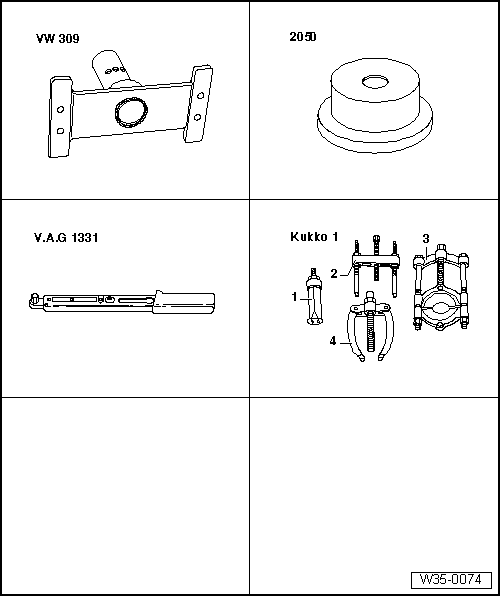
t  Support plate -VW 309-
t  Thrust piece -2050-
t  Torque wrench -V.A.G 1331-
t  -1-Internal puller -Kukko 21/7-
t  -4-Counterhold -Kukko 22/2-

It is necessary to readjust the output shaft when the following components are renewed:
t  Gearbox housing
t  Clutch housing
t  Output shaft for 1st through 4th gears
or
t  Tapered roller bearings
Adjustment overview → Chapter
Prerequisites:
l  Sealing surfaces of clutch and gearbox housings must be free of sealant.
l  When taking measurements, install only the shaft to be measured.
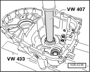
–  Press tapered roller bearing outer race with 1.70 mm thick shim into gearbox housing to stop. In the process, support gearbox housing using thrust piece -2050- directly below bearing support.
   
–  Set complete output shaft for 1st through 4th gears in clutch housing.
  N35-0239
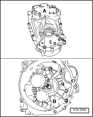
–  Set gearbox housing in place and tighten bolts -A- as well as -B- alternately and diagonally to specified torque → Item and → Item.
  N34-0992
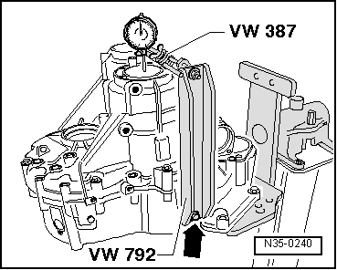
–  Set up measuring tools and secure to clutch housing using bolt -arrow-.
–  Set dial gauge (3 mm measuring range) to “0” with 1 mm preload.
–  Loosen clutch housing/gearbox housing securing bolts diagonally until output shaft or gearbox housing is free.
–  Read and note value on dial gauge (example: 0.14 mm).
  Note
t  If dial gauge indicates no value when clutch housing/gearbox housing securing bolts are loosened, install 1.95 mm shim or, if necessary, 2.20 mm shim when taking measurements.
t  Allocate shims using → Electronic parts catalogue (ETKA).
Determining thickness of shim
The specified bearing preload will be attained by subtracting the measured value (0.14 mm) from the inserted shim (1.70 mm) and adding a constant value for preload (0.20 mm).
Example:
  N35-0240
 Installed shim1.70 mm
-Measured value0.14 mm
+Preload (constant)0.20 mm
 Shim thickness1.76 mm

–  Determine thickness of shim from table → .
–  Determine part number of shim according to → Electronic parts catalogue (ETKA).
   
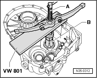
–  Remove gearbox housing and pull tapered roller bearing outer race from gearbox housing.
A - Counter support, e.g. -Kukko 22/2-
B - Internal puller 46 ... 58 mm, e.g. -Kukko 21/7-
–  Remove inserted shim (1.70 mm thick) from gearbox housing.
Table of shims
  N35-0312
 Thickness (mm) 
1.451.752.05
1.501.802.10
1.551.852.15
1.601.902.20
1.651.952.25
1.702.00 

The various thicknesses make it possible to achieve the exact shim thickness required.
   
–  Press in tapered roller bearing outer race together with correct shim (in example 1.75 mm). In the process, support gearbox housing using thrust piece -2050- directly below bearing support.
Carrying out check measurement
l  Determined shim installed.
  N35-0239
–  Set up measuring tools and secure to clutch housing using bolt -arrow-.
–  Set dial gauge (3 mm measuring range) to “0” with 1 mm preload.
–  Loosen clutch housing/gearbox housing securing bolts diagonally until output shaft or gearbox housing is free.
–  If correct shim has been selected, dial gauge will indicate a value between 0.15 mm to 0.25 mm.
  N35-0240

Output shaft for 5th, 6th and reverse gears > < Input shaft