
Leon Mk1
|
|
|
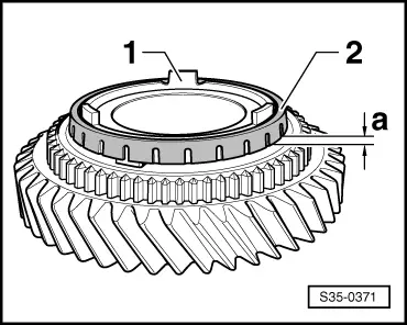
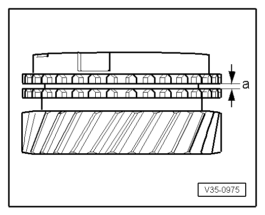
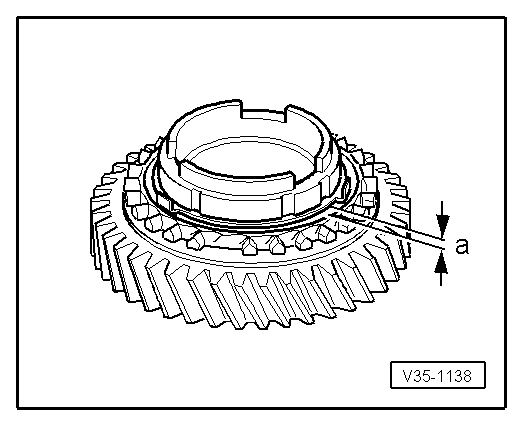
| Gap -a- | Installation (new) dimension | Wear limit |
| 1st and 2nd gears | 1.00 … 1.80 mm | 0.3 mm |
|
|
| Gap -a- | Installation (new) dimension | Wear limit |
| 1st and 2nd gears | 1.00 … 1.80 mm | 0.8 mm |
|
|
|
|
|
|
|
|
|
|
|
|
|
|
|
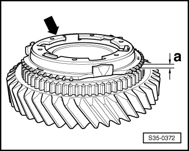
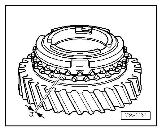
| Gap -a- | Installation (new) dimension | Wear limit |
| 4th gear | 1.0 … 1.7 mm | 0.5 mm |
|
|
|
|
|
|
| Gap -a- | Installation (new) dimension | Wear limit |
| 3rd gear | 0.75 … 1.25 mm | 0.3 mm |
|
|
| Gap -a- | Installation (new) dimension | Wear limit |
| 3rd gear | 1.2 … 1.8 mm | 0.5 mm |
|
|
|
|
|
 Note
Note
|
|