
Leon Mk1
| Clutch housing: general fitting diagram |
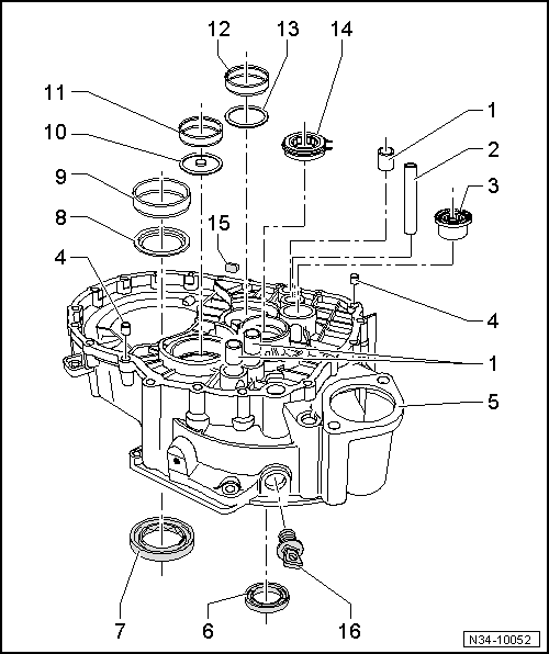
| 1 - | Bearing sleeve for the control rods |
| q | Remove → Fig. |
| q | Insert → Fig. |
| 2 - | Reverse gear prong shaft |
| q | This cannot be removed using the workshop tools |
| q | Fit into the clutch housing → Fig. |
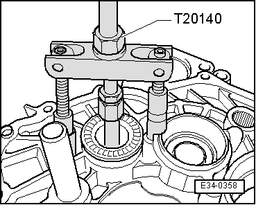
| 3 - | Point crown for the inverter shaft |
| q | Replace after each removal |
| q | Remove → Fig. |
| q | Insert → Fig. |
| 4 - | Dowel sleeves |
| q | 2 units |
| 5 - | Clutch housing |
| q | If this is replaced then the secondary differential shafts must be adjusted → Chapter |
| 6 - | Input shaft oil seal |
| q | Replacement → Chapter |
| 7 - | Insert shaft seal |
| q | Replace |
| 8 - | Packing plate |
| q | For the differential |
| q | Fitting position: the interior recesses should point towards the seal → Item |
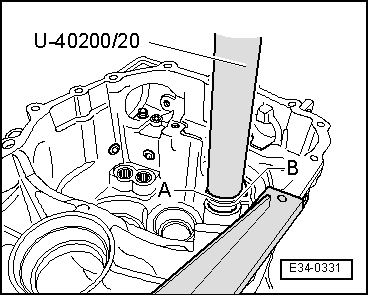
| 9 - | Outer ring of roller bearing |
| q | For the differential |
| q | Removing and fitting → Fig. |
| q | If replaced the differential must be adjusted → Chapter |
| 10 - | Oil relay washer |
| q | Fitting position: the recess of the hole should face towards the secondary shaft |
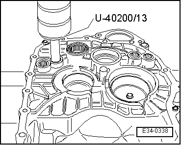
| 11 - | Outer ring of roller bearing |
| q | For secondary shaft for 1stª to 4thª gear |
| q | Removing and installing → Fig. |
| q | If replaced, the secondary shaft for 1stª/4thª gear must be readjusted → Chapter |
| 12 - | Outer ring of roller bearing |
| q | For secondary shaft for 5thª/6thª and reverse gear |
| q | Removing and installing → Fig. |
| q | If replaced, the secondary shaft for 5thª/6thª and reverse gear must be readjusted → Chapter |
| 13 - | Packing plate |
| q | For secondary shaft for 5thª/6thª and reverse gear |
| q | 0.65 mm in thickness |
| 14 - | Cylindrical roller bearing |
| q | For the input shaft |
| q | Removing and fitting → Fig. |
| 15 - | Magnet |
| q | Supported by the separation surface of the housing |
| 16 - | Cowling |
| Check the tool and equipment equivalence table according to the applicability between Seat / VW / Audi / Skoda → Chapter. |

| Special tools and workshop equipment required |
| t | Pressure tool -T20129-, see equivalent → Anchor |
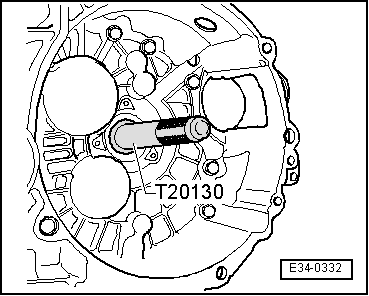
| t | Push rod -T20130-, see equivalent → Anchor |
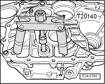
| t | Extractor kit -T20140-, see equivalent → Anchor |
| t | Extractor kit -T20143-, see equivalent → Anchor |
| t | Kit (case) -U-40200A-, see equivalent → Anchor |
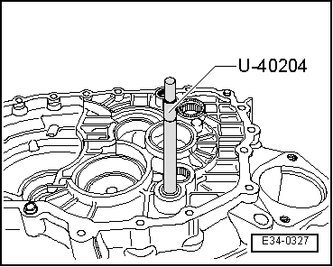
| t | Push rod -U-40204-, see equivalent → Anchor |
|
|
|
|
|
|
 Note
Note
|
|
|
|
|
|