
Leon Mk1
 Note
Note
|
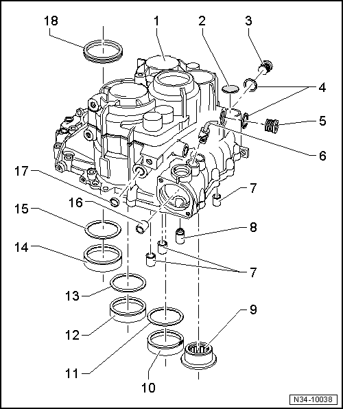
| 1 - | Gearbox casing |
| q | If this is replaced then the secondary differential shafts must be adjusted → Chapter |
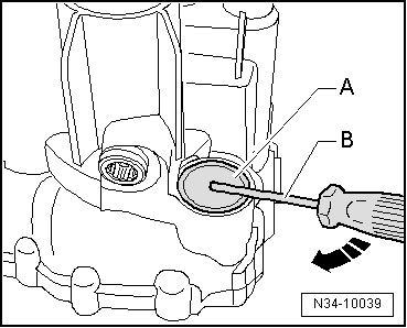
| 2 - | Cover |
| q | Removing → Fig. |
| q | Insert → Fig. |
| 3 - | Oil empty plug |
| q | Allen screw, -30 Nm |
| 4 - | Seal |
| q | Replacement |
| 5 - | Oil filler plug |
| q | Allen screw, -30 Nm |
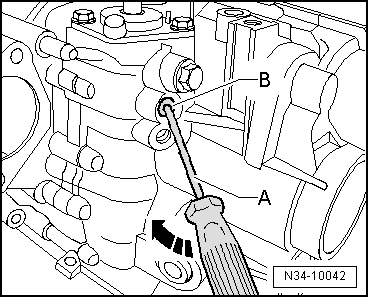
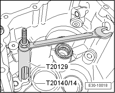
| 6 - | Locking bolt |
| q | To adjust gear selector mechanism → Chapter |
| q | This may be replaced with the gearbox without disassembling |
| q | Removing → Fig. |
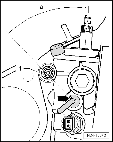
| q | Installation position → Fig. |
| q | Insert → Fig. |
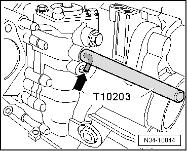
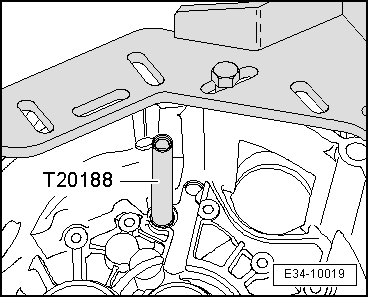
| 7 - | Bearing sleeve for the control rods |
| q | Remove → Fig. |
| q | Insert → Fig. |
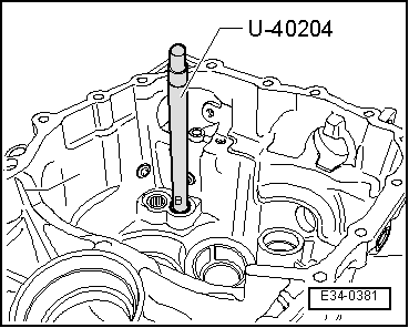
| 8 - | Insertion sleeve |
| q | Remove with the gearbox disassembled |
| q | Insert → Fig. |
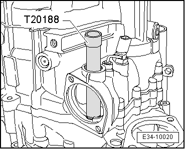
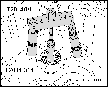
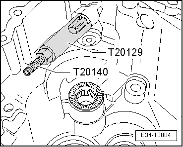
| 9 - | Point crown for the inverter shaft |
| q | Replace after removing |
| q | Remove → Fig. |
| q | Insert → Fig. |
| 10 - | Outer ring of roller bearing |
| q | For secondary shaft for 5thª/6thª and reverse gear |
| q | Removing and installing → Fig. |
| q | If replaced, the secondary shaft for 5thª/6thª and reverse gear must be readjusted → Chapter |
| 11 - | Shim |
| q | For secondary shaft for 5thª/6thª and reverse gear |
| q | Adjustment chart → Chapter |
| 12 - | Outer ring of roller bearing |
| q | For secondary shaft for 1stª to 4thª gear |
| q | Removing and installing → Chapter |
| q | If replaced, the secondary shaft for 1stª/4thª gear must be readjusted → Chapter |
| 13 - | Shim |
| q | For secondary shaft for 1stª to 4thª gear |
| q | Adjustment chart → Chapter |
| 14 - | Outer ring of roller bearing |
| q | For the differential |
| q | Removing and fitting → Chapter |
| q | If replaced the differential must be adjusted → Chapter |
| 15 - | Shim |
| q | For the differential |
| q | Adjustment chart → Chapter |
| 16 - | Bearing socket for operation mechanism shaft |
| q | Remove |
| q | Insertion |
| 17 - | Plug |
| q | Releasing |
| q | Insertion |
| 18 - | Seal |
| q | Replacement |
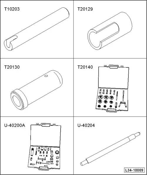
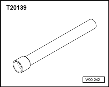
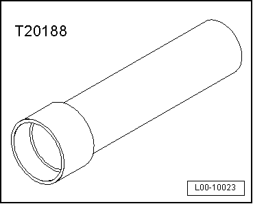
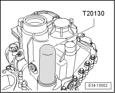
| Check the tool and equipment equivalence table according to the applicability between Seat / VW / Audi / Skoda → Chapter. |
|
|
|
|
|
|
|
|
|
|
|
|
|
|
|
|
|
|
|
|
|
|
|
|
|
|
|
|
|
|
|
|