seat Workshop Repair Guides

SEAT Workshop Service and Repair Manuals

Removal of bevel gear; vehicles with petrol engine > < Removing and installing bevel box
Removal of bevelled gear, vehicles with Diesel engine with particulate filter
Consult the equivalence table for tools and equipment according to applicability among Seat / VW / Audi / Skoda → Chapter.
   
Special tools and workshop equipment required
t  Socket wrench e/c 22 -T20202A-, see equivalent → Anchor
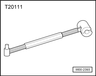
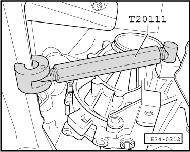
t  Socket wrench e/c 17 -T20211-, see equivalent → Anchor
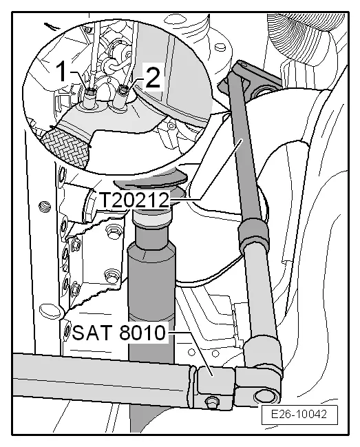
t  Articulated wrench e/c 17 -T20212-, see equivalent → Anchor
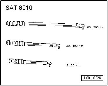
t  "Ratchet 1/2"" x 9-12" -VAG 1331/1-, see equivalent → Anchor

Special tools and workshop equipment required
   
t  Torque wrench kit -SAT 8010-, see equivalent → Anchor
  L00-10226
t  counterhold -T20111-, see equivalent → Anchor
  W00-2393
–  Uniformly detach outer -1- and inner -2- engine cover upward.
  E10-10038
–  Unscrew oxygen sensor -G39--3- with 22 mm socket wrench -T20202A- and "1/2" ratchet" x 9-12" -VAG 1331/1-.
–  Unscrew temperature sensor in front of particulate filter -G448--5- with 17 mm socket wrench -T20211- and ""1/2" ratchet" x 9-12" -VAG 1331/1-.
–  Unscrew bracket -2- for pressure lines.
–  Unscrew pressure line -4- in front of particulate filter using 17 mm socket wrench -T20211- and "1/2" ratchet" x 9-12" -VAG 1331/1-.
–  Loosen and remove clamp -1- for particulate filter.
  A26-10173
–  Unscrew pressure line -2- with 17 mm flexible head spanner -T20212-.
–  Unscrew temperature sensor in back of particulate filter -G527--1- with 17 mm flexible head spanner -T20212-.
  E26-10042
–  Remove the switching valve for the radiator for the exhaust gas recirculation -N345-- Pos. 2- from its bracket.
–  Disconnect electrical connector -1- and expose electrical line.
–  Unscrew bolts -arrows-.
–  Remove pressure sensor 1 for exhaust gas -G450- together with pressure hoses.
  Note
Disregard: -Items 3, 4, 5, 6-.
–  Raise the vehicle.
–  Remove centre sound insulation → Bodywork, exterior installation work; Rep. gr.50.
–  Remove the right half shaft → Running gear, axles, steering; Rep. gr.40
  A15-10345
–  Unbolt the exhaust system bracket -arrows-.
  A26-10131
–  Remove the bracket for the particulate filter -arrows A and B-.
  Note
The vibration damper on the front section of the exhaust pipe with particle filter should not be bent by more than 10° otherwise there is a risk of damage.
–  Partially remove front section of exhaust pipe with particulate filter and position on timing case.
  E34-10180
–  Detach clamping sleeve -1-.
–  Remove the front section of the cardan shaft → Final drive 0AV; Rep. gr.39.
  Note
When moving the engine assembly to the rear, take care that the electric cables and flexible lines are not exposed to excessive tensioning.
  A26-0734
–  Slightly move the subframe to the rear using the retaining tool -T20111-.
  E34-0212
–  Pull out and the connector -1- and remove the cable fastener on the subframe.
  N34-10504
–  Remove pendulum support from gearbox.
  Note
  N34-10973
Slackening off securing bolts for pendulum support causes engine/gearbox assembly to swing forwards slightly (towards front end). Make sure that the seal -arrow- in the flange of the propshaft is not damaged when removing and installing.
  V39-1817
–  Push oil return line to side by loosening bolts -2- and -3-.
  A21-10088
–  Unscrew the heat protection plate for the right cardan shaft from the anchorage on the bevel gear -arrow-.
  E34-10168
–  Unscrew the fixing bolts of the bevel gear on the engine -arrows 1... 3-.
–  Remove the bracket of the bevelled gear.
  N34-10717
–  Draining the oil from the bevel box -A-.
–  Remove the flange -arrow- and seal on the right side → Chapter.
  N34-11710
–  Unscrew the bottom bolts -arrows- for fixing the bevel gear to the gearbox.
–  Unscrew the top bolts for fixing the bevel gear to the gearbox.
  N34-10500
A heat shield -arrow A- is installed on top of bevel box in some vehicles.
The bolt -arrow B- can be reached from the lower side of the heat protection plate.
The bolt -arrow C- can be reached from the upper side of the heat protection plate.
–  Carefully remove the bevel gear from the gearbox and secure against falling down.
–  Take out bevel box.
  N34-10494
–  When the bevel gear has to be replaced, a check should be made if the heat protection plate -A- has been removed.
  N34-10495

Removal of bevel gear; vehicles with petrol engine > < Removing and installing bevel box