Leon Mk1
|
|
|

| Special tools and workshop equipment required |
| t | Torque wrench -VAG 1331- |
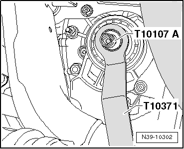
| t | Counter support -T10371- |
| t | Socket -T10107A- |
| t | Support bridge -T10323- |
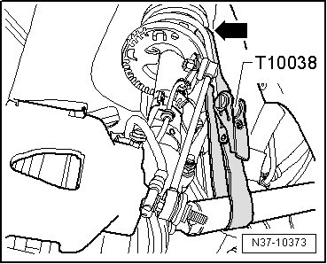
| t | Tensioning strap -T10038- |
|
|
|
|
|
|
|
|
|
|
|
|
|
|
|
|
|
|
|
|
|
|
|
|
|
|
|
|
|
|
|
|
|
|

|
|
|
| Special tools and workshop equipment required |
| t | Torque wrench -VAG 1331- |
| t | Counter support -T10371- |
| t | Socket -T10107A- |
| t | Support bridge -T10323- |
| t | Tensioning strap -T10038- |
|
|
|
|
|
|
|
|
|
|
|
|
|
|
|
|
|
|
|
|
|
|
|
|
|
|
|
|
|
|
|
|
|
|