
Leon Mk1
|
 Note
Note| t | Carry out output shaft adjustment → Chapter if the output shaft or tapered roller bearings have been renewed . |
| t | Replace both conical roller bearings together. |
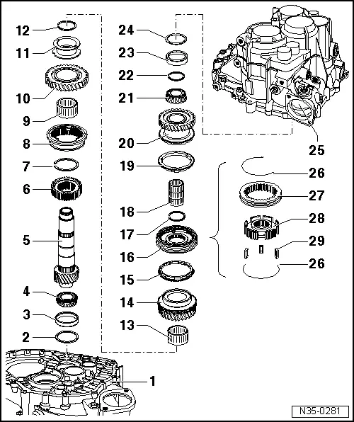
| 1 - | clutch housing |
| 2 - | Plate |
| q | Always 0.65 mm thick |
| 3 - | Outer track, roller bearing |
| q | Pulling out → Fig. |
| q | Pressing on → Fig. |
| 4 - | Tapered roller bearing inner race |
| q | Pressing out → Fig. |
| q | Pressing on → Fig. |
| 5 - | Output shaft |
| q | For 5th, 6th and reverse gears |
| q | Adjust convergence → Chapter |
| 6 - | Reverse gear synchro-hub |
| q | Pressing out → Fig. |
| q | Installation position → Fig. |
| q | Pressing on → Fig. |
| 7 - | Circlip |
| 8 - | Reverse gear locking collar |
| q | With synchro-ring |
| 9 - | Needle bearing |
| q | For reverse gear shaft |
| 10 - | Synchromeshed gear for reverse gear |
| 11 - | Drift sleeve |
| q | Release from above the reverse gear mobile pinion → Fig. |
| q | Installation position: wide shoulder of sleeve faces synchromeshed gear for reverse gear |
| q | Pressing on → Fig. |
| 12 - | Circlip |
| 13 - | Needle bearing |
| q | For 6th gear |
| 14 - | 6th speed selector gear |
| 15 - | 6th gear synchro-ring |
| q | Check for wear → Fig. |
| 16 - | Locking collar with synchronising hub for 5th and 6th gear |
| q | Press off together with 6th speed selector gear after removing circlip → Item → Fig. |
| q | Dismantling → Fig. |
| q | Assembling locking collar/synchronising hub → Fig. and → Fig. |
| q | Pressing on → Fig. |
| 17 - | Circlip |
| 18 - | Needle bearing |
| q | for 5th gear |
| 19 - | 5th gear synchro-ring |
| q | Check for wear → Fig. |
| 20 - | 5th gear mobile pinion |
| 21 - | Tapered roller bearing inner race |
| q | Pressing out → Fig. |
| q | Pressing on → Fig. |
| 22 - | Circlip |
| q | If tapered roller bearing → Item and output shaft → Item are renewed, redetermine → Fig. |
| 23 - | Outer track, roller bearing |
| q | Pulling out → Fig. |
| q | Pressing on → Fig. |
| 24 - | Shim |
| q | Determining thickness → Chapter |
| 25 - | Gearbox |
| 26 - | Spring |
| q | Installation position → Fig. |
| 27 - | Mobile element |
| 28 - | Synchro-hub |
| 29 - | Locking pieces (3 off) |
| q | Installation position → Fig. |