
Leon Mk1
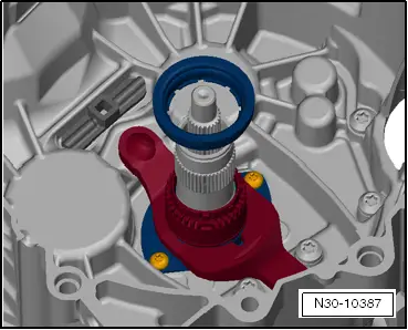
| Overview of clutch actuation: |

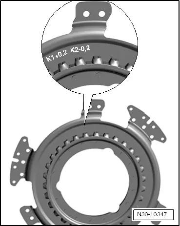
| 1 - | Shim for „K 1“ |
| q | → Chapter „Adjusting position of clutch engagement bearings K 1 and K 2“ |
| 2 - | Large engaging lever for „K 1“ |
| q | With engagement bearing |
| 3 - | Mounting |
| q | For large engaging lever „K 1“ |
| q | Is not renewed |
| 4 - | Small engagement bearings for „K 2“ |
| 5 - | Shim for „K 2“ |
| q | → Chapter „Adjusting position of clutch engagement bearings K 1 and K 2“ |
| 6 - | Upper section of bushing |
| q | Small small engaging lever „K 2“ |
| q | Is removed and installed together with lower section of bushing |
| 7 - | Small engaging lever for „K 2“ |
| q | Is removed and installed together with upper and lower section of bushing |
| 8 - | Ball head stud |
| q | Small small engaging lever „K 2“ |
| q | → Chapter „Adjusting position of clutch engagement bearings K 1 and K 2“ |
| 9 - | Bolts |
| q | 8Nm + 90° |
| q | Always replace. |
| 10 - | Lower section of bushing |
| q | Small small engaging lever „K 2“ |
| q | Is removed and installed together with upper section of bushing |
|
|
|
|
|
 Caution
|
|
 Note
Note
|
|
|
|
|
|
|
|
|
|
|
|
Note
Note
|
|
|
|
 WARNING
|
|
|
|
|
|
|
|
|
|
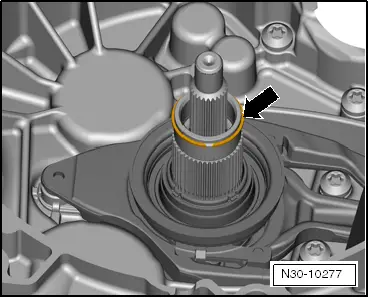
Note
|
|
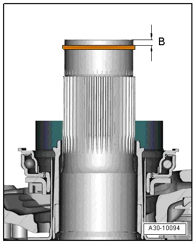
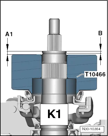
| Dimension „A 1“ | |
| – | Dimension „B“ |
| = | Actual height tolerance of clutch engagement bearing „K 1“ |
|
Note
|
|
| Height tolerance of engagement bearing „K 1“ | |
| –/+ | Clutch tolerance of clutch „K 1“ |
| = | Calculated thickness of shim „SK 1“ |
|
|
|
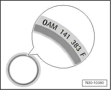
| Calculated thickness of shim mm | Available shims Thickness in mm | Part number of shim |
| 1,21 … 1,60 | 1,50 | 0AM 141 383 |
| 1,61 … 1,80 | 1,70 | 0AM 141,383 A |
| 1,81 … 2,00 | 1,90 | 0AM 141,383 B |
| 2,01 … 2,20 | 2,10 | 0AM 141 383 C |
| 2,21 … 2,40 | 2,30 | 0AM 141 383 D |
| 2,41 … 2,60 | 2,50 | 0AM 141 383 E |
| 2,61 … 2,80 | 2,70 | 0AM 141 383 F |
| 2,81 … 3,00 | 2,90 | 0AM 141 383 G |
| 3,01 … 3,20 | 3,10 | 0AM 141 383 H |
| 3,21 … 3,40 | 3,30 | 0AM 141,383 J |
| 3,41 … 3,80 | 3,50 | 0AM 141,383 K |
|
|
|
Note
|
|
|
|
|
|
|
|
|
|
|
|
|
|
Note
|
|
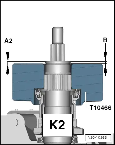
| Dimension „A 2“ | |
| – | Dimension „B“ |
| = | Actual height tolerance of clutch engagement bearing „K 2“ |
|
Note
|
|
| Height tolerance of engagement bearing „K 2“ | |
| –/+ | Clutch tolerance of clutch „K 2“ |
| = | Calculated thickness of shim „SK 2“ |
|
|
|
| Calculated thickness of shim mm | Available shims Thickness in mm |
| 0,31 … 0,90 | 0,80 |
| 0,91 … 1,10 | 1,00 |
| 1,11 … 1,30 | 1,20 |
| 1,31 … 1,50 | 1,40 |
| 1,51 … 1,70 | 1,60 |
| 1,71 … 1,90 | 1,80 |
| 1,91 … 2,10 | 2,00 |
| 2,11 … 2,30 | 2,20 |
| 2,31 … 2,50 | 2,40 |
| 2,51 … 2,70 | 2,60 |
| 2,71 … 3,30 | 2,80 |
|