|
After electrical checks
-
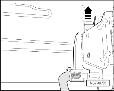
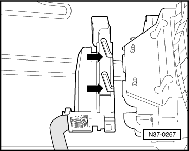
‒ → Fit multi-pin connector on control unit -J217- and lock.
When fitting ensure that the guides (arrows) are engaged on control unit pins.
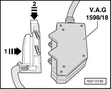
Control unit -J217- multi-pin connector (68 pin) assignment (sockets on V.A.G 1598/18)
|
1-
|
Earth (terminal 31)
|
20-
|
Road speed sender -G68-
|
|
2-
|
Vacant
|
21-
|
Gearbox speed sender -G38-
|
|
3-
|
Vacant
|
22-
|
Solenoid valve 6 -N93- supply voltage
|
|
4-
|
Vacant
|
23-
|
Supply voltage (terminal 15)
|
|
5-
|
Vacant
|
24-
|
Diagnosis K-wire
|
|
6-
|
Gearbox oil temperature (ATF) sender -G93-
|
25-
|
Vacant
|
|
7-
|
Vacant
|
26-
|
Vacant
|
|
8-
|
Vacant
|
27-
|
Vacant
|
|
9-
|
Solenoid valve 3 -N90-
|
28-
|
Vacant
|
|
10-
|
Solenoid valve 7 -N94-
|
29-
|
Selector lever lock solenoid -N110-
|
|
11-
|
Park/neutral signal
|
30-
|
Vacant
|
|
12-
|
Kickdown for air conditioner
|
31-
|
Vacant
|
|
13-
|
Ignition timing influence
|
32-
|
Vacant
|
|
14-
|
Vacant
|
33-
|
Vacant
|
|
15-
|
Brake light switch -F- signal voltage
|
34-
|
Vacant
|
|
16-
|
Kickdown switch -F8-
|
35-
|
Vacant
|
|
17-
|
Vacant
|
36-
|
Diagnosis L-wire
|
|
18-
|
Multi-function switch -F125-
|
37-
|
Vacant
|
|
19-
|
TD (revolution) signal
|
38-
|
Vacant
|
|
39-
|
Vacant
|
54-
|
Solenoid valve 2 -N89-
|
|
40-
|
Multi-function switch -F125-
|
55-
|
Solenoid valve 1 -N88-
|
|
41-
|
Throttle valve potentiometer -G69- signal1)
|
56-
|
Solenoid valve 5 -N92-
|
|
42-
|
Diesel engine revolution sensor (screening)
|
57-
|
Selector lever display
|
|
43-
|
Road speed sender -G68- (screening)
|
58-
|
Solenoid valve 6 -N93-
|
|
44-
|
Gearbox speed sender -G38- (screening)
|
59-
|
Vacant
|
|
45-
|
Supply voltage (terminal 30)
|
60-
|
Cruise control system (input terminal15)
(vacant on vehicles from 5.95)
|
|
46-
|
Vacant
|
61-
|
Cruise control system (output)
|
|
47-
|
Solenoid valve 4 -N91-
|
62-
|
Multi-function switch -F125-
|
|
48-
|
Freewheel lock valve -N87-
|
63-
|
Multi-function switch -F125-
|
|
49-
|
Vacant
|
64-
|
Engine speed sender -G28- (Diesel engine)
|
|
50-
|
Vacant
|
65-
|
Road speed sender -G68-
|
|
51-
|
Vacant
|
66-
|
Gearbox speed sender -G38-
|
|
52-
|
Vacant
|
67-
|
Solenoid valves voltage supply
|
|
53-
|
Vacant
|
68-
|
Terminal 30 (output)
|
1) Signal (contact 41) directed via engine control unit to gearbox control unit and can only be checked in "Reading measured value block" .
List of test steps (multi-pin connector with 68 pins)
Only perform test steps for the relevant component as listed in fault finding table and read measured value block.
|
Component checked
|
|
Component checked
|
|
|
Supply voltage from control unit -J217-
|
- Perform test step 1
|
Solenoid valve 7 -N94-
|
- Perform test step 10
|
|
Selector lever lock solenoid -N110-
|
- Perform test step 2 and 11
|
Kickdown switch -F8-
|
- Perform test step 12
|
|
Brake light switch -F-
|
- Perform test step 3
|
Gearbox oil temperature sender -G93- (ATF)
|
- Perform test step 13
|
|
Solenoid valve 1 -N88-
|
- Perform test step 4
|
Road speed sender -G68-
|
- Perform test step 14
|
|
Solenoid valve 2 -N89-
|
- Perform test step 5
|
Gearbox speed sender -G38-
|
- Perform test step 15
|
|
Solenoid valve 3 -N90-
|
- Perform test step 6
|
|
|
|
Solenoid valve 4 -N91-
|
- Perform test step 7
|
|
|
|
Solenoid valve 5 -N92-
|
- Perform test step 8
|
|
|
|
Solenoid valve 6 -N93-
|
- Perform test step 9
|
|
|
|