seat Workshop Repair Guides

SEAT Workshop Service and Repair Manuals

Automatic gearbox 099 4-speed self-diagnosis > < Performing self-diagnosis
Automatic gearbox 099 4WD -self-diagnosis-
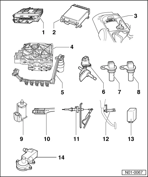
Locations of electrical/electronic components
 
N01-0067
  • Automatic gearbox control unit -J217-
    • ◆ Location => Fig.1
    • ◆ Removing => Fig. 2
    • ◆ Installing => Fig. 3
    • ◆ Control units are checked by self-diagnosis => Carrying out self-diagnosis, Page 01-24
    • ◆ The signal from throttle valve potentiometer is directed via engine control unit to gearbox control unit and can only be checked in measured value block . If a fault is indicated in the throttle valve potentiometer, then also carry out a self-diagnosis on engine control unit
    • ◆ The signal of throttle valve potentiometer is checked by self-diagnosis.
 
N01-0067
  • Engine control unit
    • ◆ Location => Fig. 4
    • ◆ Removing and installing

=> Repair Group 24

If engine or gearbox control units are replaced, the system must be brought to basic setting => page 01-48, Initiating basic setting.

  • Diagnosis connection
    • ◆ Location => Fig. 5
  • Valve body
    • ◆ Location => Fig. 6
    • ◆ The solenoid valves -N88-, -N89-, -N90-, -N91-, -N92-, -N93- and -N94- are attached to the valve body
    • ◆ Components are checked by self-diagnosis
 
N01-0067
  • Conductor strip with integrated gearbox oil temperature sender (ATF) -G93-
    • ◆ Location => Fig. 7
    • ◆ -G93- is checked by self-diagnosis
  • Multifunction switch -F125-
    • ◆ Location and removing and installing =>Fig. 8
    • ◆ Checked by self-diagnosis
  • Gearbox speed sender -G38-
    • ◆ Location and removing and installing =>Fig. 9
    • ◆ The connector T2 to wiring loom is white
    • ◆ Checked by self-diagnosis

Do not interchange connector T2 for senders -G38- and -G68-

 
N01-0067
  • Road speed sender -G68-
    • ◆ Location and removing and installing =>Fig. 10
    • ◆ The connector T2 to wiring loom is black
    • ◆ Checked by self-diagnosis

Do not interchange connector T2 for senders -G38- and -G68-

  • Solenoid for selector lever lock -N110-
    • ◆ Location => Fig. 11
    • ◆ Can be checked electrically => page 01-50
 
N01-0067
  • Cruise control switch -E45-
    • ◆ Location => Fig. 12
    • ◆ Removing and installing

=> Repair Group 94; Servicing steering column switch

    • ◆ Can be checked via reading measured value block
      => page 01-50
  • Kickdown switch -F8-
    • ◆ Location => Fig. 13
    • ◆ When removing and installing kickdown switch, remove and install the throttle cable, then adjust afterwards
    • ◆ Adjusting throttle cable

=> Repair Group 20

    • ◆ Can be checked electrically => page 01-50
 
N01-0067
  • Brake light switch -F-
    • ◆ Location: => Fig. 14
    • ◆ Removing and installing

=> Repair group 47; Assembly overview: Pedal cluster, brake pedal

    • ◆ Can be checked electrically => page 01-50
  • Relay for starter lock-out and reversing light -J226-
    • ◆ Location => Fig.15
  • Freewheel lock valve -N87-
    • ◆ Location => Fig.16
 
N37-0286

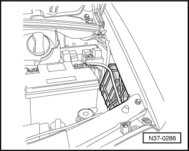
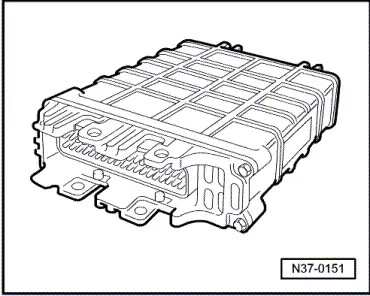
→ Fig.1    Location of automatic gearbox control unit -J217-

The control unit is located in the engine compartment, left.

 
N37-0288

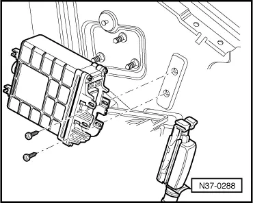
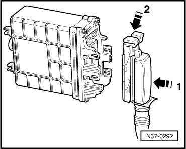
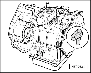
→ Fig.2    Removing automatic gearbox control unit -J217-

  • ‒ Release multi-pin connector, then pull connector off control unit.
 
N37-0292

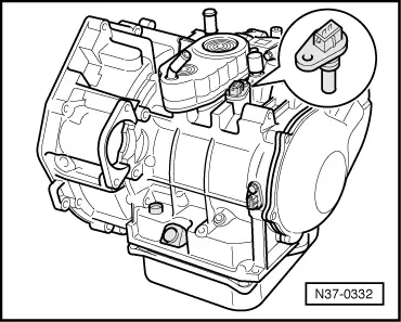
→ Fig.3    Installing automatic gearbox control unit -J217-

  • ‒ Fit multi-pin connector onto control unit -J217- pins -1- then lock multi-pin connector -2-.

 
N37-0151

→ Fig.4    Engine control unit

Location: The control unit is located behind dash panel.

Removing and installing control unit

=> Repair group 24

 
N37-0293

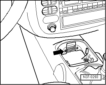
→ Fig.5    Diagnosis connections

Location: The diagnosis connection -arrow- is located in centre console.

  • ‒ Connect fault reader V.A.G 1551 and enter address word "02 Gearbox electronics" and advance until "Select function XX" indicated on display => from page 01-24.

 
N38-0051

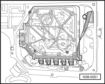
→ Fig.6    Valve body

Location: The valve body is located above oil pan.

The solenoid valves -N88-, -N89-, -N90-, -N91-, -N92-, -N93- and -N94- are attached to the valve body.

Removing and installing valve body

=> Repair group 38; Removing and installing valve chest

in booklet:

  • ◆ Workshop Manual Alhambra 1996 ä , Automatic gearbox 099 four wheel drive
 
N38-0051

→ Fig. 7    Conductor strip with integrated gearbox oil temperature sender (ATF) -G93-

Location: The conductor strip is located in the oil pan on the valve body.

The conductor strip can be changed with gearbox installed without removing the valve body.

Do not kink or damage the conductor strip.

Removing and installing conductor strip

=> Repair group 38; Removing and installing valve chest

in booklet:

  • ◆ Workshop Manual Alhambra 1996 ä , Automatic gearbox 099 four wheel drive
 
N01-0077

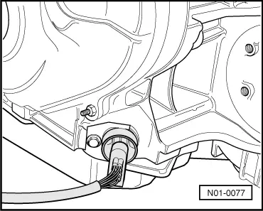
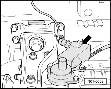
→ Fig.8    Multi-function switch -F125-

Location: The multi-function switch is located on gearbox lower section.

Removing and installing multi-function switch

  • ‒ Pull connector off multi-function switch.
  • ‒ Remove bolt and retainer.
  • ‒ Place oil tray under gearbox to catch ATF.
  • ‒ Remove multi-function switch.
  • ‒ Renew seal.

Installation is performed in the reverse order.

  • ‒ Tighten bolt to10 Nm .
  • ‒ Check connector; cover/seal must prevent ingress of moisture (visual check).
  • ‒ Check ATF level and top-up.

=> Repair group 37; Checking and topping up ATF level

in booklet:

  • ◆ Workshop Manual Alhambra 1996 ä , Automatic gearbox 099 four wheel drive
 
N37-0332

→ Fig.9    Gearbox speed sender -G38-

Location: The gearbox speed sender -arrow- is located on top of gearbox.

Removing and installing gearbox speed sender

  • ‒ Pull connector off sender.
  • ‒ Remove bolt and pull sender out.
  • ‒ Renew seal.

Installation is performed in the reverse order.

  • ‒ Tighten bolt to 10 Nm.
 
N37-0331

→ Fig.10    Road speed sender -G68-

Location: The road speed sender -arrow- is located on front of gearbox.

Removing and installing road speed sender

  • ‒ Pull black connector off sender.
  • ‒ Remove bolt and pull sender out.
  • ‒ Renew seal.

Installation is performed in the reverse order.

  • ‒ Tighten bolt to 10 Nm.
 
N37-0333

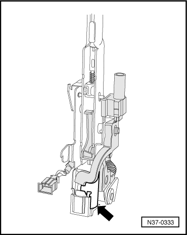
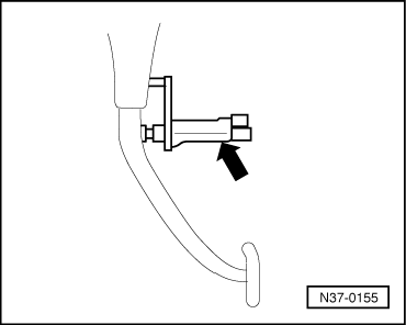
→ Fig.11    Selector lever lock solenoid -N110-

Location: The selector lever lock solenoid is located on selector lever (arrow).

Removing and installing selector lever lock solenoid

=> Repair group 37; Servicing selector lever mechanism

in booklet:

  • ◆ Workshop Manual Alhambra 1996 ä , Automatic gearbox 099 four wheel drive

 
N37-0285

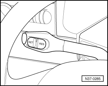
→ Fig.12    Cruise control system switch -E45-

Location: Cruise control switch is located on steering column switch.

Removing and installing cruise control switch

=> Servicing steering column switch; Repair group 94

 
N37-0154

→ Fig.13    Kickdown switch -F8-

Location: Kickdown switch (arrow) is integrated into accelerator cable and is located on bulk head in engine compartment.

Removing and installing kickdown switch

  • ‒ Remove the accelerator cable to remove and install the kickdown switch, then reinstall cable and adjust.

=> Repair group 20; Adjusting accelerator cable

 
N37-0155

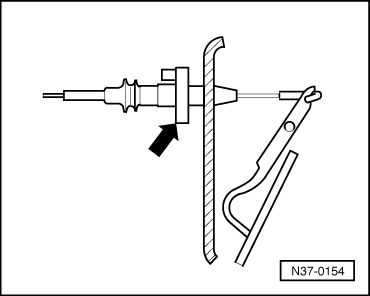
→ Fig.14    Brake light switch -F-

Location: Brake light switch (arrow) is located on pedal cluster.

Removing and installing brake light switch

=> Repair group 47; Assembly overview: Pedal cluster, brake pedal

 
N01-0078

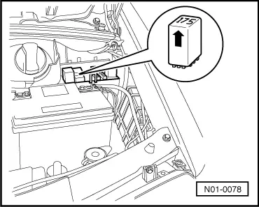
→ Fig.15    Relay for starter inhibitor and reversing light -J226-

Location: Relay located on relay carrier in engine compartment, left.

Relay can be marked with the number "175" or "150" (arrow).

 
N01-0068

→ Fig.16    Freewheel lock valve -N87-

Location: The freewheel lock valve is located in freewheel lock actuator on rear final drive.

Check function of valve as follows:

=> Repair group 39; Checking function of freewheel lock

in booklet:

  • ◆ Workshop Manual Alhambra 1996 ä , Automatic gearbox 099 four wheel drive

Automatic gearbox 099 4-speed self-diagnosis > < Performing self-diagnosis