
Leon Mk1
| Electrical and electronic components and their locations |

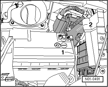
| 1 - | Automatic gearbox control unit -J217- |
| q | Location → Fig.. |
| q | Removing → Fig.. |
| q | Installing → Fig.. |
| q | Is checked by self-diagnosis → Automatic gearbox 099 - 4-speed; Rep. Gr.01. |
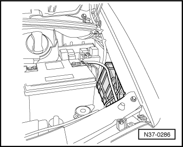
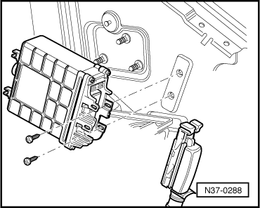
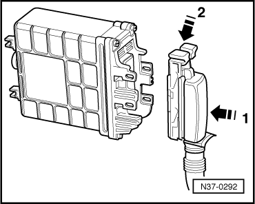
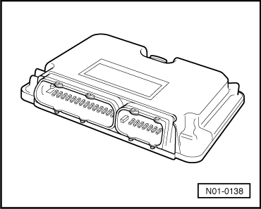
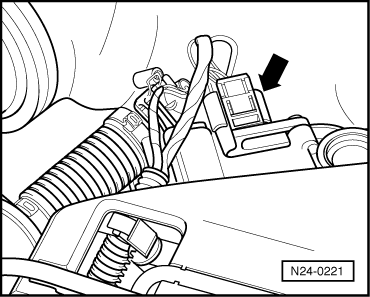
| 2 - | Engine control unit |
| q | Location in vehicles before 05.00 → Fig.. |
| q | Location in vehicles after 06.00 → Fig.. |
| q | Removing and installing → Rep. Gr.23 or → Rep. Gr.24 of the corresponding engine code letter. |
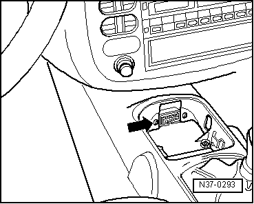
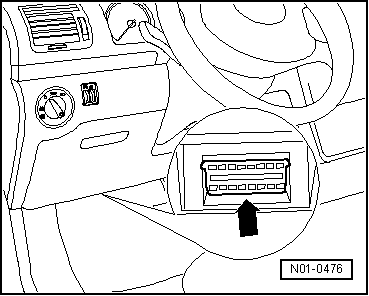
| 3 - | Diagnostic connection |
| q | Location in vehicles before 05.00 → Fig.. |
| q | Location in vehicles after 06.00 → Fig.. |
| 4 - | Vehicle speed sender -G68- |
| q | Location and removing and installing → Chapter. |
| 5 - | Gearbox speed sender -G38- |
| q | Location and removing and installing → Chapter. |
| 6 - | Multi-function switch -F125- |
| q | Location and removing and installing → Chapter. |
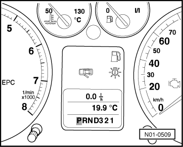
| 7 - | Selector lever position display -Y6- |
| q | Location → Fig.. |
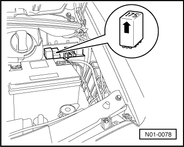
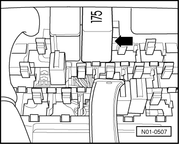
| 8 - | Starter inhibitor and reversing light relay -J226- |
| q | Location in vehicles before 05.00 → Fig.. |
| q | Location in vehicles after 06.00 → Fig.. |
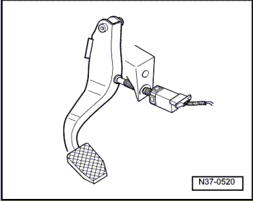
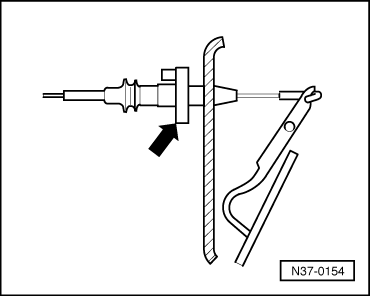
| 9 - | Brake light switch -F- |
| q | Location and removing and installing → Fig.. |
| 10 - | Kickdown switch -F8- |
| q | Location in vehicles without EPC → Fig.. |
| q | Location in vehicles with EPC → Fig.. |
| 11 - | Cruise control system switch -E45- |
| q | Location → Fig.. |
| 12 - | Selector lever lock solenoid -N110- |
| q | Location and removing and installing in vehicles before 05.00 → Chapter. |
| q | Location and removing and installing in vehicles after 06.00 → Chapter. |
| 13 - | Tiptronic switch -F189- |
| q | Removing and installing → Chapter. |
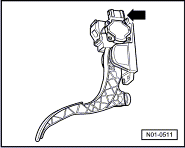
| 14 - | Throttle valve potentiometer -G69- or accelerator pedal position sender -G79- |
| q | Location → Fig.. |
| q | For more information → Automatic gearbox 099 - 4-speed; Rep. Gr.01. |
| 15 - | Conductor strip with integrated gearbox oil temperature sender -G93- |
| q | Location: On valve body. |
| q | Removing and installing → Chapter. |
| 16 - | Valve body |
| q | Location: On gearbox. |
| q | Removing and installing → Chapter. |
|
|
|
|
|
|
|
|
|
|
|
|
|
|
|

|
|
|
|
|
|
|
|
|
|
|
|
|
|
|