
Leon Mk1
|
|
|
|
|
| t | Output gear must be removed for dismantling and assembling parking lock → Chapter „Removing and installing drive shaft“. |
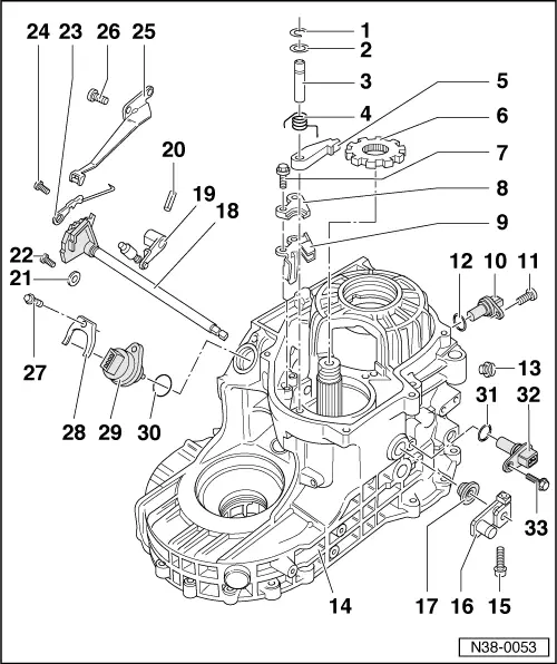
| 1 - | Circlip |
| q | Always renewing. |
| 2 - | Washer |
| 3 - | Shaft for detent lever |
| q | Is secured by circlip and bearing cap of drive shaft. |
| q | Depending on design, with groove for circlip. |
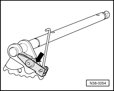
| 4 - | Return spring |
| q | Installing → Fig.. |
| 5 - | Detent lever |
| q | Inserting with return spring → Fig.. |
| 6 - | Parking lock gear |
| q | Rounded side faces teeth of drive shaft. |
| 7 - | Bolt, 14 Nm |
| 8 - | Support plate |
| q | Installing → Fig.. |
| 9 - | Guide plate |
| q | Inserting before supporting plate → Fig.. |
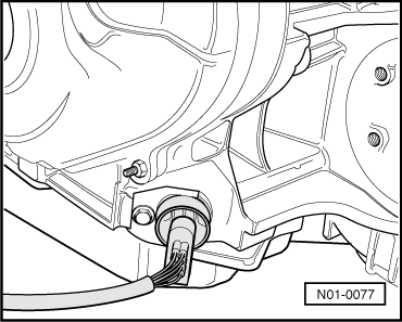
| 10 - | Vehicle speed sender -G68- |
| q | Removing and installing → Fig.. |
| q | Is checked by self-diagnosis in vehicle → Self-diagnosis for automatic gearbox 099 - 4-speed; Rep. Gr.01. |
| 11 - | Bolt, 10 Nm |
| 12 - | O-ring |
| q | Always renewing. |
| 13 - | Bolt, 15 Nm |
| q | With oil seal. |
| q | Always renewing. |
| 14 - | Gearbox housing |
| 15 - | Bolt, 10 Nm |
| 16 - | Lever |
| q | For selector shaft. |
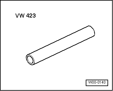
| 17 - | Oil seal |
| q | Levering out with screwdriver. |
| q | Driving in flush with -VW 423-. |
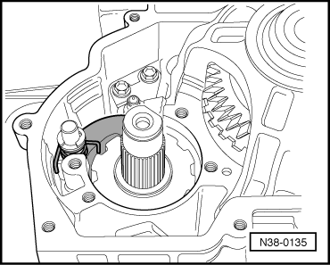
| 18 - | Selector shaft with selector segment and detent segment |
| q | Inserting together with engaging lever. |
| q | Removing and installing → Fig.. |
| 19 - | Engaging lever |
| q | Inserting together with selector shaft and detent segment. |
| 20 - | Spring pin |
| q | Driving in after inserting engaging lever → Fig.. |
| q | Driving out with a drift. |
| 21 - | Lock washer |
| q | Removing and installing → Fig.. |
| 22 - | Bolt, 10 Nm |
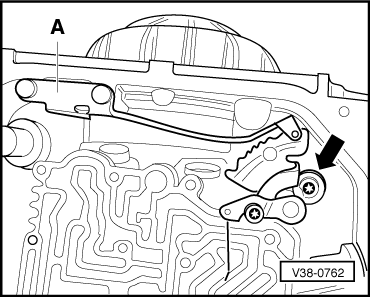
| 23 - | Spool valve control |
| q | Adjusting → Chapter, removing and installing valve body. |
| 24 - | Bolt, 10 Nm |
| 25 - | Spring for selector segment |
| 26 - | Bolt, 10 Nm |
| 27 - | Bolt, 10 Nm |
| 28 - | Retainer |
| q | For multi-function switch. |
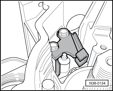
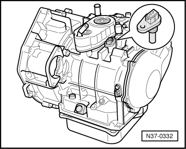
| 29 - | Multi-function switch -F125- |
| q | Removing and installing → Fig.. |
| q | Is checked by self-diagnosis in vehicle → Self-diagnosis for automatic gearbox 099 - 4-speed; Rep. Gr.01. |
| 30 - | O-ring |
| q | Always renewing. |
| 31 - | O-ring |
| q | Always renewing. |
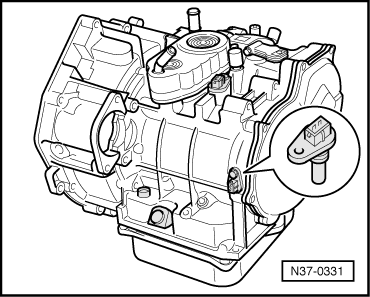
| 32 - | Gearbox speed sender -G38- |
| q | Removing and installing → Fig.. |
| q | Is checked by self-diagnosis in vehicle → Self-diagnosis for automatic gearbox 099 - 4-speed; Rep. Gr.01. |
| 33 - | Bolt, 10 Nm |
|
|
|
|
|
|
|
|
|
|
|
|
|
|