
Leon Mk1
|
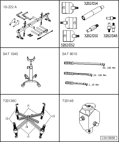
| Special tools and workshop equipment required |
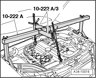
| t | Support bracket -10-222 A- |
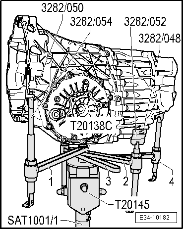
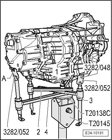
| t | Adjustment plate -3282/052-, adjustment plate -3282/048-, extension -3282/050- and extension -3282/054- |
| t | Hydraulic jack -SAT 1040-, see equivalent → Anchor |
| t | Torque wrench kit -SAT 8010-, see equivalent → Anchor |
| t | Gearbox support -T20138C-, see equivalent → Anchor |
| t | Base -T20145- |
|
|
|
|
|
|
 Caution
|
|
|
|
|
|
|
|
 Note
Note |
|
|
|
|
|
|
|
|
|
|
|
Note
|
|
|
|
|
|
|
|
|
|
Note
|
|
Note
|
|
|
|
Note
|
|
|
|
|
|
|
|