seat Workshop Repair Guides

SEAT Workshop Service and Repair Manuals

Selector lever handle and gear operation mechanism cover: Assembly overview > < Gearbox, vehicles with petrol engine: Removing and installing
Electric/electronic components and assembly positions
   
Electric/electronic components and assembly positions
1 - Control unit for automatic control unit -J217-
q   Fitting location → Fig.
q   The control unit is checked using the self-diagnosis
q   Removing and installing → Chapter>>>>>>>>
2 - Hydraulic control unit
q   Fitting location → Fig.
q   Valves are checked via self-diagnosis.
q   Removing and installing → Chapter>>>>>>>>
3 - Selector mechanism cover
q   Removing and installing → Chapter>>>>>>>>
4 - Tiptronic switch -F189-
q   Installation location: Integrated in printed circuit located in selector mechanism cover
q   Comprises 3 Hall sensors actuated by a magnet on transverse slide of masking panel
q   If malfunctions occur in the Tiptronic switch -F189-, first check that the magnet on the transverse slide of the sliding cover is secured properly. If necessary, renew sliding cover. The printed circuit board must only be replaced after checking the wiring.
q   Removing and installing → Chapter>>>>>>>>
5 - Selector lever locking solenoid -N110-
q   Fitting location → Fig.
q   Removing and installing → Chapter>>>>>>>>
6 - Diagnostics connection
q   Fitting location → Fig.
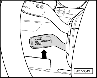
7 - Switch for cruise control system -E45-
q   Fitting location → Fig.
q   Removing and installing → Electrical system; Rep. gr.94
8 - Starter inhibitor relay -J207-
q   Fitting location → Fig.
9 - Voltage supply relay, terminal 87/ automatic gearbox relay -J60-
q   Fitting location → Fig.
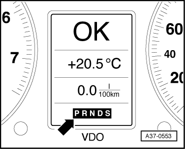
10 - Gear selector position indicator -Y6-
q   Fitting location → Fig.
q   A fully illuminated gear selection indicator indicates a simple fault
q   If the gear display flashes, there is a critical fault.
q   A blank display indicates defective wiring or a defective selector lever position display -Y6-.
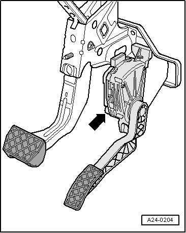
11 - Kickdown switch -F8-
q   Not fitted as a separate component: on vehicles with petrol engine this function is performed by accelerator pedal position sender -G79- and accelerator pedal position sender 2 -G185-. The two senders are integrated in the accelerator pedal module; fitting location → Fig.
q   In vehicles with diesel engine, this deals with a switch that generates a module together with the accelerator pedal position sender -G79- which is integrated in the accelerator pedal module; Fitting location → Fig.
q   Signal recognition in engine control unit, signal transmission from engine control unit to gearbox control unit via CAN bus
q   Removing and installing accelerator pedal module → Rep. gr.20
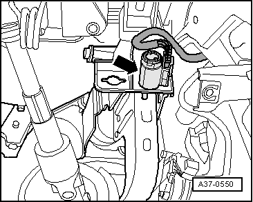
12 - Brake light switch -F-
q   Fitting location → Fig.
q   Signal recognition in engine control unit, signal transmission from engine control unit to gearbox control unit via CAN bus
q   Removing and installing → brake system; Rep. gr.46.

   
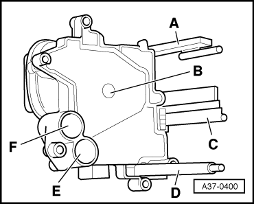
Control unit for automatic control unit -J217-
t  Installation location: the control unit for automatic gearbox -J217- is mounted direct on the hydraulic control unit on the rear side of the gearbox.
The following components are integrated into the control unit:
A - Gearbox output speed sender -G195- and gearbox output speed sender 2 -G196-
B - Gearbox oil temperature sender -G93-
C - Multifunction switch -F125-
D - Gearbox input speed sender -G182-
E - Automatic gearbox hydraulic pressure sender 1 -G193-
F - Automatic gearbox hydraulic pressure sender 2 -G194-
Control unit for automatic gearbox -J217-: Removing and installing → Chapter.
  A37-0400
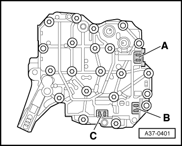
Hydraulic control unit
t  Installation location: The hydraulic control unit is bolted to rear end of gearbox. The control unit for automatic gearbox -J217- is bolted direct to the hydraulic control unit.
A - Connector for automatic gearbox pressure control valve 1 -N215-
B - Connector for automatic gearbox pressure control valve 2 -N216-
C - Connector for solenoid valve 1 -N88-
The following valves are integrated into the hydraulic control unit (not shown in illustration):
t  Automatic gearbox pressure control valve 1 -N215- (clutch solenoid valve)
t  Automatic gearbox pressure control valve 2 -N216- (solenoid valve for transmission ratio)
t  Solenoid valve 1 -N88- (clutch cooling/safety shut-off).
t  Clutch cooling valve
t  Minimum pressure valve
t  Pressure limiting valve
t  Clutch control valve
t  Control-pressure valve
  Note
t  The valves are monitored via self-diagnosis.
t  Description and function of the individual valves → No.228.
Hydraulic control unit: Removing and installing → Chapter.
  A37-0401
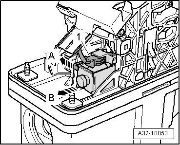
Selector lever locking solenoid -N110-
t  Installation location: The selector lever lock solenoid -N110- is located in the selector mechanism -arrow-.
  A37-10053
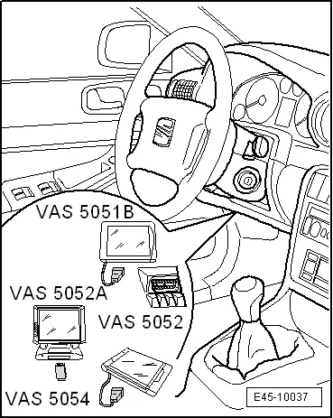
Diagnostics connection
t  Installation location: The diagnostic connector is located below the knee padding on the left side of the steering wheel.
  E45-10037
Switch for cruise control system -E45-
t  Installation location: Cruise control system switch is located at steering column switch.
  A37-0549
Gear selector position indicator -Y6-
t  Installation location: Integrated into dash panel.
  Note
The selector lever position display -Y6- can only be renewed together with the instrument cluster.
  A37-0553
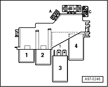
Starter inhibitor relay -J207-
t  Installation location: On the relay carrier in the plenum chamber electronics box.
Voltage supply via terminal 87 differs as follows:
2 - With Motronic current supply relay -J271- - for vehicles with petrol engine
3 - Terminal 30 voltage supply relay -J317- - vehicles with diesel engine
4 - Starter inhibitor relay -J207-
  A97-0246
Brake light switch -F-
t  Installation location: Brake light switch -arrow- is located at pedal cluster.
  Note
To ensure a good fit, the switch should only be mounted once.
  A37-0550
Kickdown switch -F8-
t  Installation location: In accelerator pedal module -arrow-.
  Note
t  On vehicles with petrol engine accelerator pedal position sender -G79- and accelerator pedal position sender 2 -G185- perform the function of the kickdown switch -F8-.
t  On vehicles with diesel engine the kick-down switch -F8- is incorporated in accelerator pedal position sender -G79-.
  A24-0204

Selector lever handle and gear operation mechanism cover: Assembly overview > < Gearbox, vehicles with petrol engine: Removing and installing