seat Workshop Repair Guides

SEAT Workshop Service and Repair Manuals

Checking oil pressure and oil pressure switch > < Servicing valve gear
4-cyl. Diesel engine, Mechanics
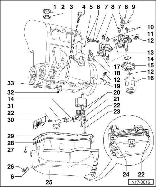
Removing and installing parts of the lubrication system

Notes:

  • ◆ If large quantities of metal particles or other deposits (caused, for example, by partial seizure of the crankshaft or conrod bearings) are found in the engine oil when performing repairs, clean the oil passages thoroughly and renew the oil cooler in order to prevent further damage from occurring later.
  • ◆ The oil level must not be above the max. mark - danger of damage to catalyst!

Checking oil pressure

Oil system capacity1):

    without oil filter 3.8 ltrs.
    with oil filter 4.3 ltrs.

    1)    Up-to-date figures:

=> Exhaust emissions test binder

Engine oil specifications:

Only use engine oil conforming to VW standard 50500.

 
N17-0016

Part I

Part II removing and installing oil supply pipe => page 17-9

  • Cap
  • Gasket
    • ◆ Renew if damaged
  • Guide
    • ◆ Pull off to extract oil
  • Dipstick
    • ◆ The oil level must not be above the max. mark!
    • ◆ Area above shaded zone up to max. mark: Do not top up with engine oil!
    • ◆ Oil level in shaded zone: Engine oil can be topped up
    • ◆ Area min. mark up to shaded zone: Top-up engine oil
 
N17-0016
  • Oil supply pipe
    • ◆ To turbocharger
    • ◆ With oil filter bracket item 17
    • ◆ Removing and installing
  • Seal
    • ◆ Renew
  • Banjo bolt
    • ◆ Tightening torque => page 17-9, item 4
  • 0.25 bar oil pressure switch (F22), 25 Nm
    • ◆ Identification: blue
    • ◆ Wiring: blue/black
    • ◆ Fitting location for engine codes AFN, AVG:
      gearbox side in cylinder head
    • ◆ Checking => Page 17-13
    • ◆ If sealing ring is leaking nip open and replace.
  • Oil supply pipe
    • ◆ To turbocharger
    • ◆ With oil filter bracket item 11
    • ◆ Removing and installing
 
N17-0016
  • 0.9 bar oil pressure switch (F1), 25 Nm
    • ◆ Grey
    • ◆ Wiring: yellow
    • ◆ Checking => Page 17-13
    • ◆ If sealing ring is leaking nip open and replace.
  • Oil filter bracket
  • 25 Nm
  • Restrictor
  • O-ring
    • ◆ Renew
  • Oil cooler
    • ◆ Coat contact area to flange, outside the seal, with AMV 188 100 02
    • ◆ Ensure clearance to adjacent components
    • ◆ See note
      => Page 17-1
 
N17-0016
  • Oil filter
    • ◆ Loosen with strap wrench
    • ◆ Tighten by hand
    • ◆ Observe installation instructions on oil filter
  • Oil filter bracket
  • Gasket
    • ◆ Renew
  • Clamp
  • Gears
    • ◆ Checking backlash
      => Fig. 1
    • ◆ Checking axial clearance
      => Fig. 2
  • Oil pump cover with pressure relief valve
    • ◆ Opening pressure: 5.7...6.7 bar
  • 10 Nm
  • 20 Nm
  • Spreader rivet
 
N17-0016
  • Sump cover
  • Oil drain plug, 30 Nm
    • ◆ Renew plug with attached seal
  • 20 Nm
    • ◆ Remove and install both rear bolts gearbox end with jointed spanner 3185
  • Sump
    • ◆ Clean sealing surface before installing
  • Gasket
    • ◆ Renew
    • ◆ Before fitting gasket coat sump flange/cylinder block flange with "D2"
  • Baffle plate
  • Suction pipe
    • ◆ Clean strainer if soiled
 
N17-0016
  • 10 Nm
    • ◆ Insert with AMV 188 100 02
  • Oil spray jet
    • ◆ For piston cooling
 
V17-0005

→ Fig. 1    Checking oil pump backlash

    New: 0.05 mm

    Wear limit: 0.20 mm

 
V17-0006

→ Fig. 2    Checking oil pump axial clearance

    Wear limit: 0.15 mm

 
N17-0235

Part II

Assembly overview

  • Oil supply pipe
    • ◆ To turbocharger
  • Union nut, 22 Nm
    • ◆ When loosening and tightening counter-hold connection
  • Seal
    • ◆ Renew
  • Banjo bolt, 25 Nm
  • Clip
  • 10 Nm
  • Bracket
  • 25 Nm
    • ◆ Renew
  • 10 Nm
  • 10 Nm
 
N17-0235

Assembly sequence

Removing

  • ‒ Remove noise insulation.
  • ‒ Place drain tank V.A.G 1306 underneath.
  • ‒ Remove air cleaner housing.
  • ‒ Remove union nut -2- or banjo bolt -4- from oil filter bracket.
  • ‒ Remove bolt -6-.
  • ‒ Remove union nut -2- from exhaust turbocharger.
  • ‒ Remove bolt -9- from bracket -7-.
  • ‒ Remove nut -8- and take off bracket -7-.
  • ‒ Remove oil supply line -1-.
 
N17-0235

Installing

Install in reverse order. When doing this note the following:

Warning!
The installation of oil supply line must be carried out as described below.
  • ‒ Screw bracket -7- with nut -8- loosely to exhaust manifold.
  • ‒ Tighten union nut -2- or banjo bolt -4- on oil filter bracket by hand.
  • ‒ Tighten union nut -2- on turbocharger by hand.
  • ‒ Tighten union nut -2- or banjo bolt -4- on oil filter bracket to tightening torque.
 
N17-0235
  • ‒ Tighten union nut -2- on exhaust turbocharger to tightening torque.
  • ‒ Position clamps -5- on oil supply line.
  • ‒ Tighten bolts -6- and -9- to tightening torque.
  • ‒ Tighten nut -8- to tightening torque.

Checking oil pressure and oil pressure switch > < Servicing valve gear