seat Workshop Repair Guides

SEAT Workshop Service and Repair Manuals

Coolant hose connection diagram > < Parts of cooling system body side
4-Cyl. injection engine (2 valve), Mechanics
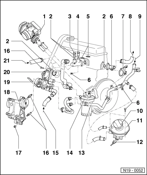
Removing and installing parts of cooling system
Parts of cooling system - engine side
 
N19-0052
  • Throttle valve control part (J338)
  • O-ring
    • ◆ Renew
  • Air conditioner cut-off thermo switch (F163) and radiator fan 3rd speed thermo switch (F165)
    • ◆ Brown, 4 pin
    • ◆ On vehicles with air conditioning

=> Heating, air conditioning; Repair group 87

  • Coolant temperature sender (G62)
    • ◆ With coolant temperature gauge sender (G2)
 
N19-0052
  • Retaining clip
  • 10 Nm
  • Bracket
  • To heat exchanger
  • From heat exchanger
  • Cap
    • ◆ Check with coolant system tester V.A.G 1274 and adapters V.A.G 1274/1A and V.A.G 1274/7
    • ◆ The pressure relief valve must open at a pressure of 1.4 ...1.6
  • Expansion tank
    • ◆ Perform leak test of cooling system with cooling system tester V.A.G 1274 and adapter V.A.G1274/7
 
N19-0052
  • Connector
    • ◆ Black, 2 pin
  • Coolant pipe
  • Oil cooler
    • ◆ Removing and installing
      , Item 12
  • From bottom of radiator
    • ◆ , Item 6
  • 20 Nm + 1/4 turn (90 °) further
    • ◆ Renew
  • 30 Nm
  • Bracket
    • ◆ For alternator
 
N19-0052
  • V-belt/ribbed belt
    • ◆ Removing and installing ribbed belt
    • ◆ Adjusting V-belt tension:

=> Running gear; Repair group 48; Assembly overview: vane pump, reservoir and hydraulic pipes

  • Coolant pump
    • ◆ Dismantling and assembling => Page 19-10
  • To top of radiator
    • ◆ , Item 3

Coolant hose connection diagram > < Parts of cooling system body side