seat Workshop Repair Guides

SEAT Workshop Service and Repair Manuals

Removing and installing parts of fuel supply system > < Activated charcoal filter system
4-cyl. injection engine (2 valve without intermediate shaft), Mechanics
Electronic power control (EPC)
Checking accelerator pedal position sender
 
W20-0036

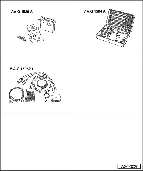
Special tools, workshop equipment, test and measuring appliances and auxiliary items required

  • ◆ V.A.G 1526 Hand multimeter
  • ◆ V.A.G 1594 A Adapter set
  • ◆ V.A.G 1598/31 Test box
  • ◆ Fault reader V.A.G 1551 or vehicle system tester V.A.G 1552 with cable V.A.G 1551/3
  • ◆ Current flow diagram

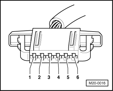
Function

Both accelerator pedal position senders -G79- and -G185- on the accelerator pedal pass the driver's requirements on to the engine control unit independently of one another. Both senders are installed together in a housing.

Check conditions

  • ● The fuses must be OK.
  • ● The battery voltage must be at least 11.5 V.

Test sequence

  • ‒ Connect fault reader V.A.G 1551 (V.A.G 1552) and with ignition switched on select engine electronics control unit with the "Address word" 01:

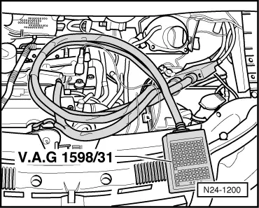
=> Repair group 01; General to self-diagnosis: Connecting fault reader

 
→ Indicated on display:
Rapid data transfer    HELP
Select function XXX
  • ‒ Press keys 0 and 8 for the function "Read measured value block" and confirm entry with Q key.
 
→ Indicated on display:
Read measured value block
Input display group number XXX
  • ‒ Press keys 0, 6 and 2 for the "Display group number 62" and confirm entry with Q key.
 
→ Indicated on display:
(1...4 = Display zones)
Read measured value block 62    ⇒
    1    2    3    4
  • ‒ Check specification of sender 1 (G79) at idling speed limit stop in display zone 3.
        Specification: 6...96 %
  • ‒ Check specification of sender 2 (G185) at idling speed limit stop in display zone 4.
        Specification: 3...48 %

Note:

The engine control unit calculates the voltage values of the angle sender in percent relative to 5 Volt and displays these as a percentage figure (5 Volt supply voltage equates to 100 %).

  • ‒ Operate the accelerator pedal slowly until fully depressed and observe the angle sender figures in display zones 3 and 4:
  • The percent figures in display zone 3 must rise evenly. The tolerance range of 6...96 % is not covered completely.
  • The percent figures in display zone 4 must rise evenly. The tolerance range of 3...48 % is not covered completely.

Note:

The figure displayed in display zone 3 must always be approximately double that displayed in display zone 4.

  • ‒ Press the ⇒key.
  • ‒ Press keys 0 and 6 for the function "End output" and confirm entry with the Q key.
  • ‒ Switch off ignition.

If the display does not indicate as described:

  • ‒ Check accelerator pedal position sender voltage supply and wiring connections .

Checking voltage supply and wiring to control unit

  • ‒ Pull 6-pin connector off accelerator pedal position sender.
  • ‒ Switch ignition on.
 
M20-0016
  • ‒ → Connect multimeter to measure voltage at the following contacts of the connector:
        Contact 1 + earth
        Contact 1 + 5
        Contact 2 + earth
        Contact 2 + 3
        Specification: minimum 4.5 V
  • ‒ Switch off ignition.

If the specifications are not obtained:

  • ‒ First check whether a coded radio is fitted. If this is the case obtain the anti-theft coding.
  • ‒ Remove battery.
 
N24-1200
  • ‒ → Connect test box V.A.G 1598/31 to control unit wiring harness. The engine control unit remains disconnected.

 
M20-0016
  • ‒ → Check wiring for open circuit between test box and 6-pin connector using current flow diagram.
        Contact 1+ socket 72
        Contact 2+ socket 73
        Contact 3+ socket 36
        Contact 4+ socket 35
        Contact 5+ socket 33
        Contact 6+ socket 34
        Wire resistance: max. 1.5 ω
  • ‒ Additionally check wires for short to one another, to vehicle earth and to battery positive.
        Specification: ∞ω

If no fault is detected in the wiring:

  • ‒ Renew accelerator pedal position sender
    , item 4
  • ‒ Interrogating and erasing fault memory:

=> Repair group 01; Fault memory; Interrogating and erasing fault memory of engine control unit

Vehicles with automatic gearbox

  • ‒ On vehicles with automatic gearbox the gearbox control unit must be matched additionally:

=> Automatic gearbox 099 self-diagnosis; Repair group 01; Performing self-diagnosis; Initiating basic setting

Removing and installing parts of fuel supply system > < Activated charcoal filter system