seat Workshop Repair Guides

SEAT Workshop Service and Repair Manuals

Engine lubrication > < Servicing valve gear
5-cyl. injection engine, (4-valve), Mechanics
Removing and installing cylinder head
Adjusting valve timing
 
W13-0107

(Install timing chain)

Special tools, workshop equipment, test and measuring appliances and auxiliary items required

  • ◆ T10068 Camshaft bar
  • ◆ T10069 Counter-holder
  • ◆ V.A.G 1331 Torque wrench (5...50 Nm)
  • ◆ V.A.G 1332 Torque wrench (40...200 Nm)
  • ◆ AMV 188 001 02 Sealant

Work sequence

Warning!
When doing any repair work, especially in the engine compartment, pay attention to the following due to the cramped conditions:
  • ◆ Route all the various lines (e.g. for fuel, hydraulics, activated charcoal filter system, coolant, refrigerant, brake fluid and vacuum pipes and hoses) and electrical wiring so that the original positions are restored.
  • ◆ Ensure sufficient clearance to all moving or hot components.

Note:

The following work sequence description is for an engine which has been removed. You can start with the adjustments at the relevant position depending on how for the engine has been dismantled.

Install roller chain and chain tensioner with tensioning plate for intermediate shaft drive:

 
N13-0584
  • ‒ → Set/check position of crankshaft relative to intermediate shaft.
    To position: align
        ground down tooth on drive sprocket -B-
        with the bearing joint (TDC No.1 Cyl.).
  • ‒ Install both pins without collar for guide rail -2- and tighten to
        10 Nm.

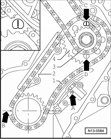
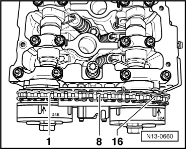
Note:

Observe direction of rotation marks on used roller chain =>Page13-9, Fig.1

  • ‒ Install guide rail -2- with roller chain -1- and both chain sprockets -3- and -4-.
        Mark on roller chain sprocket -4-
        must align with the notch -C- or -D- on the
        thrust washer of the intermediate shaft.

Take note when installing that the roller chain runs completely straight in the guide plate from the crankshaft to intermediate shaft.

 
N13-0584
  • ‒ Tighten sprockets -3- and -4- on the intermediate shaft by hand.

Note:

Take note that all chain sprocket securing screws/bolts must be renewed.

  • ‒ Now install the chain tensioner on the opposite side.
  • ‒ To do this the locking teeth of the chain tensioner -A- must be released with a small screwdriver and the tensioning plate pressed against the chain tensioner.
  • ‒ Install chain tensioner in this position and tighten to
        8 Nm.
 
N13-0559
  • ‒ → Lock vibration damper with counter-holder T10069.
 
N13-0584
  • ‒ → Tighten new securing bolts for intermediate shaft sprockets -3- and -4- to
        60 Nm + 90° (1/4 turn).
    (The additional turn can be performed in several steps.)
  • ‒ Remove counter-holder T10069.
  • ‒ Check again the position of the crankshaft -B- to the intermediate shaft -C- or -D-.
  • ‒ Set engine to No. 1 cylinder TDC again.

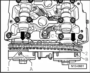
Install camshaft driver roller chain:

  • ‒ Position the camshafts installed in cylinder head to TDC No. 1 cylinder.
 
N15-0335

Note:

  • ‒ → If necessary, turn camshafts -arrows- to proper position using 32 mm open-jaw spanner. Camshaft bar T10068 must be removed while this is done.
 
N15-0341
  • ‒ → Now the camshaft bar T10068 must be able to be inserted in both shaft slots.

Note:

If the cylinder head is removed:

  • ‒ Installing cylinder head Removing and installing cylinder head.
  • ‒ Lay camshaft roller chain over intermediate shaft sprocket.
  • ‒ Route chain between tensioning bar and guide rail in direction of control housing.
  • ‒ First install inlet side camshaft adjuster with camshaft chain laid over it.
 
N15-0433
  • ‒ → Position both camshaft adjusters (identification: 24E on inlet side and 32A on exhaust side) on ends of camshafts -arrows-.
 
N13-0647

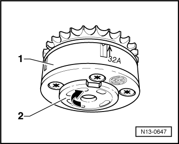
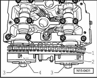
Note:

→ The exhaust camshaft adjuster -1- can be turned in two directions. When installing it, make sure that the sender wheel -2- of the Hall sender (G163) is turned to stop in direction of -arrow-. The distance between the two ground-down teeth of the inlet and exhaust camshaft adjusters must be exactly 16 rollers of the camshaft roller chain.

  • ‒ Install exhaust camshaft adjuster with camshaft roller chain laid over it.

 
N13-0661
  • ‒ → Marks -A- and -B- on camshaft adjusters must line up with notches -arrows- on control housing -C-.
  • ‒ The ground-down tooth -1- or -2- of the camshaft adjuster likewise faces the notch in the control housing -C-.
  • ‒ Tighten new securing bolts for camshaft adjusters by hand.

Note:

 
N13-0660

The distance between the two ground-down teeth of camshaft adjuster sprocket must be 16 rollers.

  • ‒ Remove camshaft bar T10068.
  • ‒ Turn crankshaft two full turns in engine D.O.R. and check valve timing .

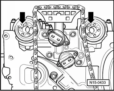
Note:

When the crankshaft is turned, the tensioner plate must be pressed against the camshaft roller chain by hand instead of with chain tensioner.

If marks do not align:

  • ‒ Repeat timing adjustment.
 
N15-0335

If marks do not agree:

  • ‒ → Hold each camshaft which is to be tightened with a 32 mm open-end spanner -arrow-.

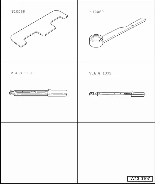
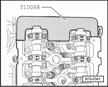
Note:

The camshaft bar T10068 must be removed while this is done.

 
N15-0431
  • ‒ → Tighten new securing bolts -3- for inlet and exhaust camshaft adjusters -4- and -2- to
        60 Nm + 1/4 turn (90°).
    (The additional turn can be performed in several steps.)
  • ‒ Coat sealing surface of sealing flange with sealant AMV 188 001 02 and install. Tighten securing bolt to
        8 Nm.
  • ‒ Renew seal on sealing flange
    => Page 13-22, item 8.
  • ‒ Now prepare the cylinder head gasket for assembly Fig. 2.
  • ‒ Coat sealing surface of cover with AMV 188 001 02.
  • ‒ Lubricate O-Ring for oil channel seal and insert into cover.
  • ‒ Install cover, insert all securing bolts and tighten lightly.
  • ‒ First tighten M8 securing bolts to
        23 Nm
    then M6 securing bolts to
        8 Nm.
  • ‒ Install chain tensioner for camshaft roller chain and tighten to
        40 Nm.
  • ‒ Turn crankshaft two full turns in engine D.O.R. and check valve timing again => Page 15-33.
  • ‒ Install cylinder head cover and intake manifold => Page 15-14, Removing and installing cylinder head cover.
  • ‒ Check camshaft adjustment
    => Page 15-77.

Engine lubrication > < Servicing valve gear