|
Notes:
-
◆ When stripping and assembling the engine, secure it to support clamp VW 313 optionally with engine bracket 3269 or VW 540 and supplementary set 540/1 B.
-
◆ If when repairing an engine, metal shavings or large quantities of small metal particles caused, for example, by partial seizure of crankshaft and conrod bearings are found in the engine oil, one must apart from thoroughly cleaning oil passages, renew all oil spray jets, the oil non-return valve, the oil cooler and oil filter element to prevent consequential damage.
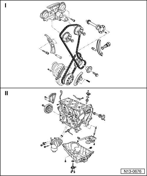
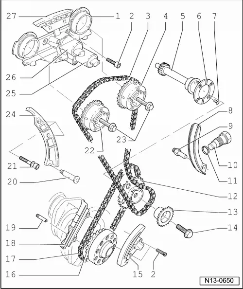
I
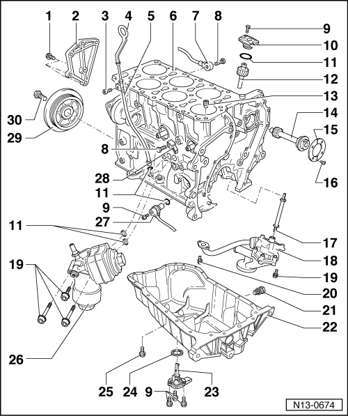
II
|