seat Workshop Repair Guides

SEAT Workshop Service and Repair Manuals

Servicing injection system > < Checking components
Motronic injection and ignition system (0.2 l engine)
Checking additional signals
Checking signal from brake light switch and brake pedal switch

Special tools, workshop equipment, testers, measuring instruments and auxiliary items required

  • ◆ Fault reader V.A.G 1551 or vehicle system tester V.A.G 1552 with cable V.A.G 1551/3
  • ◆ Test box V.A.G 1598/31
  • ◆ Hand multimeter V.A.G 1526 or multimeter V.A.G 1715
  • ◆ Adapter set V.A.G 1594
  • ◆ Current flow diagram
 
N01-0485

Test conditions

  • ● → Fuses No. 3 and 15 must be OK.

Test sequence

  • ‒ Connect the fault reader V.A.G 1551 (V.A.G 1552). Then switch ignition on and select engine control unit with the "Address word" 01.
    (Connecting fault reader and selecting engine control unit .)
 
→ Indicated on display:
Rapid data transfer    HELP
Select function XX
  • ‒ Press keys 0 and 8 for the function "Read measured value block" and confirm entry with Q key.
 
→ Indicated on display:
Read measured value block
Input display group number XXX
  • ‒ Press keys 0, 6 and 6 for "display group 66" and confirm with Q key.
 
→ Indicated on display:
Read measured value block 66    ⇒
    1    2    3    4
  • ‒ Observe display in display zone 2:
    (3rd and 4th positions from left)
        Specification: x x 0 0
  • ‒ Depress brake pedal fully and observe display in display zone 2.
        Specification: x x 1 1
  • ‒ Press the ⇒key.
  • ‒ Press keys 0 and 6 for the "End output" function and confirm input with the Q key.
  • ‒ Switch off ignition.

If the specification is not obtained:

 
N24-1231
  • ‒ Remove the shelf on driver's side:

=> General body repairs, interior; Repair group 68; Dash panel; Removing driver's side shelf

  • ‒ Pull the connector off brake light/brake pedal switch.
  • ‒ → Connect the multimeter to measure resistance between contacts 1 and 4.
        Specification: ∞ ω (no continuity)
  • ‒ Depress brake pedal.
        Specification: approx. 0 ω
  • ‒ Connect the multimeter to measure resistance between contacts 2 and 3.
        Specification: approx. 0 ω
 
A24-0200
  • ‒ Depress the brake pedal.
        Specification: ∞ ω (no continuity)

If the specifications are not attained:

  • ‒ Replace the brake light/brake pedal switch.

If the specifications are obtained:

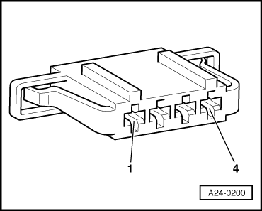
  • ‒ → Connect multimeter to measure voltage between contact 1 and earth.
        Specification: at least 11.5 V
  • ‒ Switch ignition on.
  • ‒ Connect the multimeter to measure voltage between contact 2 and earth.
        Specification: at least 11.5 V

If the specifications are not obtained:

  • ‒ Check wiring between 4-pin connector contacts 1 and 2 and multi-function unit using current flow diagram.

=> Current flow diagrams, Electrical fault finding and Fitting locations binder

If the specification is obtained:

  • ‒ Remove battery.
 
N24-1200
  • ‒ → Connect test box V.A.G 1598/31 to control unit wiring harness. The engine control unit remains disconnected.

 
A24-0200
  • ‒ → Check wiring for open circuit between test box and 4-pin connector using current flow diagram.
        Contact 2 and test box socket 55
        Contact 4 and test box socket 56
        Wire resistance: max. 1.5 ω
  • ‒ Additionally check wires for short to one another.
  • ‒ Additionally check the wiring for short to battery positive or earth.

Servicing injection system > < Checking components