seat Workshop Repair Guides

SEAT Workshop Service and Repair Manuals

Checking additional signals > < Engine control unit
Motronic injection and ignition system (0.2 l engine)
Checking components
Checking throttle valve control part

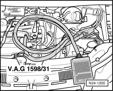
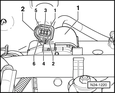
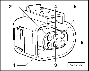
Components of throttle valve control part (J338):
Throttle valve drive (G186), angle sender 1 for throttle valve drive (G187) and angle sender 2 for throttle valve drive (G188).

Note:

If the throttle valve control part is replaced, the new control part must without fail be adapted to the engine control unit .

On vehicles fitted with an automatic gearbox the gearbox control unit must also be adapted:

=> Self-diagnosis for automatic gearbox 099; Repair group 01; Performing self-diagnosis; Initiating basic setting

Special tools, workshop equipment, testers, measuring instruments and auxiliary items required

  • ◆ Fault reader V.A.G 1551 or vehicle system tester V.A.G 1552 with cable V.A.G 1551/3
  • ◆ Test box V.A.G 1598/31
  • ◆ Hand multimeter V.A.G 1526 or multimeter V.A.G 1715
  • ◆ Adapter set V.A.G 1594
  • ◆ Current flow diagram

Check conditions

  • ● The fault memory has been interrogated => Page 01-17, interrogating fault memory of engine control unit.
  • ● All electrical consumers, e.g. lights and rear window heating must be switched off
  • ● If the vehicle is equipped with an air conditioning system, this must be switched off.
  • ● The battery voltage must be at least 11.5 V.
  • ● Throttle valve not damaged or dirty.
  • ● Coolant temperature must be at least 80 °C, =>display group 04, display zone 3.

Test sequence

  • ‒ Connect the fault reader V.A.G 1551 (V.A.G 1552). Then switch ignition on and select engine control unit with the "Address word" 01.
    (Connecting fault reader and selecting engine control unit => Page 01-9.)
 
→ Indicated on display:
Rapid data transfer    HELP
Select function XX
  • ‒ Press keys 0 and 8 for the function "Read measured value block" and confirm entry with Q key.
 
→ Indicated on display:
Read measured value block
Input display group number XXX
  • ‒ Press keys 0, 6 and 2 for the "Display group number 62" and confirm entry with Q key.
 
→ Indicated on display:
(1...4 = Display zones)
Read measured value block 62    ⇒
    1    2    3    4
  • ‒ Check throttle valve angle from sender 1 (G187) at idling stop in display zone 1
        Specification: 3...25 %
  • ‒ Check throttle valve angle from sender 2 (G188) at idling stop in display zone 2.
        Specification: 97...75 %
  • ‒ Depress accelerator slowly to full throttle position and observe angles displayed in display zones 1 and 2:
  • The percentage indicated in display zone 1 must increase evenly, although the tolerance range 3...93 % will not be fully exploited.
  • The percentage figure in display zone 2 must decrease evenly, although the tolerance range 97...3 % will not be fully exploited.

Notes:

  • ◆ The reason why the display in display zone 1 increases and the display in display zone 2 decreases is because the potentiometers (angle senders) in the throttle valve control part run in opposite directions.
  • ◆ The percentage indicated in display zones 1 and 2 must always total approx. 100 %.
  • ◆ This means that the voltage of one angle sender moves towards 5 volts. (The more the throttle valve is opened the higher the voltage; percentage figure increases).
  • ◆ Whilst the voltage of angle sender 2 decreases from 5 volts towards 0 volts. (The more the throttle valve is opened the lower the voltage; percentage figure decreases).

If the displays do not indicate as described:

  • ‒ Press ⇒key.
 
N24-1200
  • ‒ Press keys 0 and 6 for the function "End output" and confirm entry with the Q key.
  • ‒ Switch off ignition.
  • ‒ Remove battery.
  • ‒ → Connect test box V.A.G 1598/31 to control unit wiring harness. The engine control unit remains disconnected.
  • ‒ Measure resistance of throttle valve drive between test box sockets 117 + 118
        Specification: 3...200 ω

If the specification is not obtained:

  • ‒ Replace throttle valve control part (J338).
  • ‒ Adapt engine control unit again => Page 24-111

If the specification is obtained:

  • ‒ Check voltage supply of throttle valve control part and wiring to control unit => Page 24-43.
  • ‒ Check the accelerator pedal position sender.

=> Repair group 20; Electronic engine output regulation (electronic accelerator (EPC)); Checking accelerator pedal position sender

If the voltage supply and wiring is OK:

 
N24-1220
  • ‒ Renew engine control unit => Page 24-108.

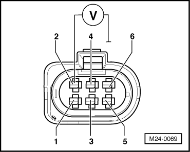
Checking voltage supply and wiring to control unit

  • ‒ → Pull the 6-pin connector -2- off the throttle valve control part -1-.

 
M24-0068
  • ‒ → Connect multimeter to measure voltage at contacts 2 and 6.
  • ‒ Switch on ignition.
        Specification: min. 4.5 V
  • ‒ Switch off ignition.
 
M24-0069
  • ‒ → Connect multimeter to measure voltage at connector contact 2 and earth.
  • ‒ Switch on ignition.
        Specification: min. 4.5 V
  • ‒ Switch off ignition.

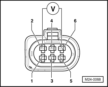
If the specifications are not attained:

 
N24-1200
  • ‒ Remove battery.
  • ‒ → Connect test box V.A.G 1598/31 to control unit wiring harness. The engine control unit remains disconnected.
 
A24-0139
  • ‒ → Check wiring for open circuit between test box socket and connector using current flow diagram:
        Contact 1 and test box socket 92
        Contact 2 and test box socket 83
        Contact 3 and test box socket 117
        Contact 4 and test box socket 84
        Contact 5 and test box socket 118
        Contact 6 and test box socket 91
        Wire resistance: max. 1.5 ω
  • ‒ Additionally check wiring for short to one another, and for short to battery positive or earth.
    Specification: ∞ω

Note:

When servicing connectors only gold-plated contacts are to be used.

If no fault is detected in the wiring:

  • ‒ Check engine control unit voltage supply => Page 24-104.

Checking additional signals > < Engine control unit