-
‒ Remove battery.
-
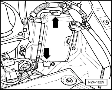
‒ → Unclip the control unit from the retaining frame -arrows- and pull out to left.
-
‒ Release connector from control unit and pull off.
-
‒ Insert new control unit and press to the right.
-
‒ Install battery.
-
‒ Adapt new control unit to throttle valve control part and exhaust gas recirculation valve => Page 24-111
-
‒ Adapt new control unit to the electronic immobilizer.
=> Electrical system self-diagnosis; Repair group 01
-
‒ On vehicles with cruise control system: Check whether this function has been enabled (activated) => Page 01-9. If "G" is not evident in the control unit identification, activate the cruise control system.
=> Current flow diagrams, Electrical fault finding and Fitting locations binder
Vehicles with automatic gearboxes:
-
‒ Adapt control unit for automatic gearbox:
=> Self-diagnosis for automatic gearbox 099; Repair group 01; Performing self-diagnosis; Initiating basic setting
-
‒ Learning kick-down point => Page 24-116
Continued for all vehicles
-
‒ Then subsequently interrogate the fault memory of the new engine control unit and erase the fault memory if necessary.
-
‒ Perform idling check
=> Page 24-82
-
‒ Carry out test drive.
- During the road test the following operating conditions must be fulfilled:
-
‒ The coolant temperature must exceed 80 °C .
-
‒ When the temperature is reached, the operating conditions
Idling
Part throttle
Enrichment
Full throttle
Overrun
must be attained several times.
-
‒ Again interrogate the control unit fault memory.
|