seat Workshop Repair Guides

SEAT Workshop Service and Repair Manuals

Fault memory > < Connecting fault reader
Motronic injection and ignition system (0.2 l engine)
Final control diagnosis
Performing final control diagnosis

The final control diagnosis activates the following components in the stated sequence:

1. Activated charcoal filter solenoid valve 1 -N80

2. Exhaust gas recirculation valve -N18

3. Secondary air pump relay -J299

4. Injector, cylinder 1 -N30

5. Injector, cylinder 3 -N32

6. Injector, cylinder 4 -N33

7. Injector, cylinder 2 -N31

Special tools, workshop equipment, testers, measuring instruments and auxiliary items required

  • ◆ Fault reader V.A.G 1551 or vehicle system tester V.A.G 1552 with cable V.A.G 1551/3
  • ◆ Test box V.A.G 1598/31
  • ◆ Adapter set V.A.G 1594
  • ◆ Hand multimeter V.A.G 1526 or multimeter V.A.G 1715
  • ◆ Diode test lamp V.A.G 1527
  • ◆ Current flow diagram

Test conditions

 
N01-0485
  • ● → All fuses must be OK.
  • ● Voltage supply for Motronic (J271) OK
  • ● Ignition on, engine not running

Notes:

  • ◆ The final control diagnosis can only be carried out if the engine is stationary and ignition switched on.
  • ◆ The final control diagnosis will be aborted if the engine is started or a rotational impulse is recognised.
  • ◆ During the final control diagnosis the individual final controls will be activated for approx. 60 seconds or until advancing to the next final control by pressing the ⇒ button.
  • ◆ The final control diagnosis can be aborted by pressing the C key so that it need not be continued with the ⇒key to the end. This is especially important because the injectors can be actuated with the ⇒key according to the firing order and inject fuel.
  • ◆ The electric fuel pump will run during the complete final control diagnosis.
  • ◆ The final controls are checked acoustically or by touching.
  • ◆ The final control diagnosis will be aborted after 60 seconds, if ⇒key is not pressed again.
  • ◆ Run engine briefly first if there is a requirement to repeat final control diagnosis.

Work sequence

  • ‒ Connect the fault reader V.A.G 1551 (V.A.G 1552). Then switch ignition on and select engine control unit with the "Address word" 01.
    (Connecting fault reader and selecting engine control unit .)
 
→ Indicated on display:
Rapid data transfer    HELP
Select function XX
  • ‒ Operate fault reader taking into account the information on the display:
  • ‒ Press keys 0 and 3 for the function "Final control diagnosis".
 
→ Indicated on display:
Rapid data transfer    Q
03 Final control diagnosis

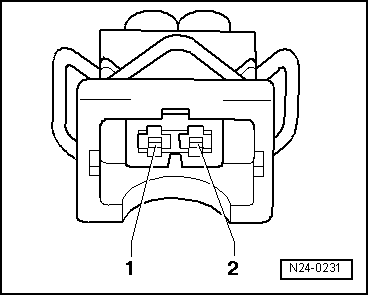
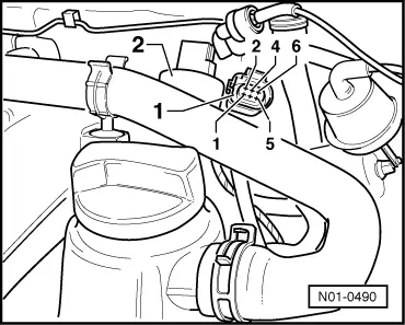
Activating activated charcoal filter solenoid valve 1 (N80):

  • ‒ Confirm input with Q key.
 
→ Indicated on display:
Final control diagnosis    ⇒
Fuel tank vent valve -N80
  • The activated charcoal filter solenoid valve 1 must click until the next final control is activated by pressing ⇒key.

If the solenoid valve does not click:

 
N01-0489
  • ‒ → Pull connector -1- off solenoid valve -2- and connect diode test lamp V.A.G 1527 with aux. cables from V.A.G 1594 to disconnected connector.
        The LED must flash

LED flashes:

  • ‒ Press the C key now to abort the final control diagnosis.

 
→ Indicated on display:
Final control diagnosis was aborted
  • ‒ Switch off ignition.
  • ‒ Renew solenoid valve.

=> Repair group 20; Activated charcoal filter system; Removing and installing parts of activated charcoal filter system

LED does not flash:

  • ‒ Press the C key to abort the final control diagnosis.
 
→ Indicated on display:
Final control diagnosis was aborted
  • ‒ Switch off ignition.
 
N24-1200
  • ‒ Remove battery.
  • ‒ → Connect test box V.A.G 1598/31 to control unit wiring harness. The engine control unit remains disconnected.

 
N24-0231
  • ‒ → Check wire between test box socket 64+2 pin connector contact 2 for open circuit using current flow diagram.
        Wire resistance: max. 1.5 ω
  • ‒ Additionally check wire for short to battery positive and earth.
  • ‒ Check wire between 2 pin connector contact 1 and fuel pump relay (J17) for open circuit using current flow diagram.
        Wire resistance: max. 1.5 ω

If no fault is detected in the wiring:

  • ‒ Renew engine control unit => Page 24-108.

Activate exhaust gas recirculation valve (N18):

  • ‒ Press ⇒key.
 
→ Indicated on display:
Final control diagnosis    ⇒
Exhaust gas recirculation valve -N18
  • The exhaust gas recirculation valve (N18) must click until the next final control is activated by pressing the ⇒ key (max. 60 seconds).
 
N01-0490

If the exhaust gas recirculation valve does not click:

  • ‒ → Pull 6-pin connector -1- off exhaust gas recirculation valve and connect diode test lamp using aux. cables from V.A.G 1594 to contacts 1 and 5.
        The LED must flash

LED flashes:

  • ‒ Press the C key now to abort the final control diagnosis.
 
→ Indicated on display:
Final control diagnosis was aborted
  • ‒ Switch off ignition.
  • ‒ Replace exhaust gas recirculation valve (N18)

=> Rep.-Gr. 26; Exhaust gas recirculation system

  • ‒ Adapt the engine control unit to the exhaust gas recirculation valve => Page 24-111.

LED does not flash:

  • ‒ Press the C key now to abort the final control diagnosis.
 
→ Indicated on display:
Final control diagnosis was aborted
  • ‒ Switch off ignition.

 
N01-0490
  • ‒ → Connect multimeter to measure voltage on 6-pin connector contact 1 and earth.
  • ‒ Switch on ignition.
        Specification: min. 11.5 V

If the specification is not attained:

 
N01-0486
  • ‒ → Check wiring to Motronic current supply relay -J271- (on lower relay carrier behind multi-function unit, relay position 25).

=> Current flow diagrams, Electrical fault finding and Fitting locations binder

If the specification is obtained:

  • ‒ Switch off ignition.

 
N24-1200
  • ‒ Remove battery.
  • ‒ → Connect test box V.A.G 1598/31 to control unit wiring harness. The engine control unit remains disconnected.
 
N01-0490
  • ‒ → Check wiring for open circuit between 6-pin connector contact 5 and test box socket 114.
        Wire resistance: max. 1.5 ω
  • ‒ Additionally check wire for short to battery positive and earth.
        Specification: ∞ω

If no fault is detected in the wiring:

  • ‒ Renew engine control unit => Page 24-108.

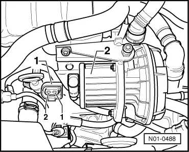
Activating secondary air pump relay (J299):

  • ‒ Press ⇒key.
 
→ Indicated on display:
Final control diagnosis    ⇒
Secondary air pump relay -J299
  • The secondary air pump relay (J299) activates the secondary air pump motor, and this must run at intervals until the next control element is activated by pressing the ⇒ key.

If the secondary air pump motor (V101) does not run at intervals:

 
N01-0488
  • ‒ → Pull 2 pin connector -1- off secondary air pump motor -2- and connect diode test lamp V.A.G 1527 with aux. cables from V.A.G 1594 to disconnected connector.
        The LED must flash

LED flashes:

  • ‒ Press the C key to abort the final control diagnosis.
 
→ Indicated on display:
Final control diagnosis was aborted
  • ‒ Switch off ignition.
  • ‒ Renew secondary air pump motor (V101):

=> Repair group 26; Secondary air system; Removing and installing parts of secondary air system

If the LED does not flash but the secondary air pump relay clicks:

  • ‒ Press the C key to abort the final control diagnosis.
 
→ Indicated on display:
Final control diagnosis was aborted
  • ‒ Switch off ignition.
 
N24-1026
  • ‒ → Check wiring for open circuit between secondary air pump motor (V101) contact 1 and body earth.
        Wire resistance: max. 1.5 ω

If no wiring fault is detected:

 
N01-0486
  • ‒ → Check fuse for secondary air pump relay (J299) (on lower relay carrier behind multi-function unit):

=> Current flow diagrams, Electrical fault finding and Fitting locations binder

 
N01-0486
  • ‒ → Pull secondary air pump relay (J299) out of lower relay carrier of multi-function unit, relay position 22.

Notes:

  • ◆ If tools are necessary to pull relays or control units out of the relay plate, first disconnect battery earth strap.
  • ◆ Before disconnecting battery earth strap obtain code for radios with anti-theft coding.

 
N01-0484
  • ‒ → Check wire between secondary air pump motor (V101) contact 2 and contact 2 on relay plate for open circuit referring to current flow diagram.
        Wire resistance: max. 1.5 ω

If no wiring fault is detected:

  • ‒ Using current flow diagram check the voltage supply (terminal 30) for secondary air pump relay (J299).

If voltage supply is OK:

  • ‒ Renew secondary air pump relay (J299).

If the LED does not flash and the secondary air pump relay does not click:

  • ‒ Press the C key to abort the final control diagnosis.
 
→ Indicated on display:
Final control diagnosis was aborted
  • ‒ Switch off ignition.
 
N01-0486
  • ‒ → Pull secondary air pump relay (J299) out of lower relay carrier of multi-function unit, relay position 22.

Notes:

  • ◆ If tools are necessary to pull relays or control units out of the relay plate, first disconnect battery earth strap.
  • ◆ Before disconnecting battery earth strap obtain code for radios with anti-theft coding.
 
N01-0484
  • ‒ → Connect the diode test lamp V.A.G 1527 B using adapter cables from V.A.G 1594 to contacts 3 and 4 on the relay plate.
  • ‒ Initiate final control diagnosis again and activate secondary air pump relay (J299).
        The LED must flash.

LED flashes:

  • ‒ Press the C key to abort the final control diagnosis.
 
→ Indicated on display:
Final control diagnosis was aborted
  • ‒ Switch off ignition.
  • ‒ Renew secondary air pump relay (J299).

LED does not flash:

 
N01-0484
  • ‒ → Connect the diode test lamp V.A.G 1527 B using adapter cables from V.A.G 1594 to contact 4 of relay plate and body earth.
        The LED must light up, when fuel pump is still
        running.

LED does not light-up:

  • ‒ Check wiring for open circuit between relay plate contact 4 and fuel pump relay using current flow diagram.

LED lights up:

  • ‒ Press the C key to abort the final control diagnosis.
 
→ Indicated on display:
Final control diagnosis was aborted
  • ‒ Switch off ignition.
  • ‒ Remove battery.
 
N24-1200
  • ‒ → Connect test box V.A.G 1598/31 to control unit wiring harness. The engine control unit remains disconnected.
  • ‒ Check the wire for open circuit between test box socket 66 and contact 3 on the relay plate using current flow diagram.
        Wire resistance: Max. 1.5 ω

If no wiring fault is detected:

  • ‒ Replace engine control unit
    => Page 24-108.

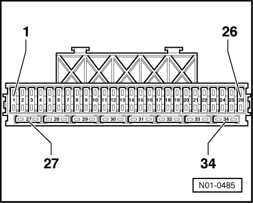
Activate injectors (N30...N33):

  • ‒ Press ⇒key.
 
→ Indicated on display:
Final control diagnosis    ⇒
Injector cylinder 1 -N30
  • ‒ Press ⇒key.
 
→ Indicated on display:
Final control diagnosis    ⇒
Injector cylinder 1 -N30
  • Injector, cylinder No. 1 (N30) must click five times.

Note:

The fuel pump must run and the flow noise must be distinctly audible at the fuel pressure regulator. If the fuel pump does not run, check activation.

=> Repair group 20; Removing and installing parts of the fuel system; Checking fuel pump

  • ‒ Press the ⇒key each time to advance to the next injector.
  • ‒ In this way, all injectors can be checked one after the other in firing order.

If one of the injectors is not activated (does not click):

  • ‒ Checking injectors => Page 24-65.
  • ‒ Press ⇒key.
 
→ Indicated on display:
Final control diagnosis    ⇒
END
  • ‒ Press ⇒key.
 
→ Indicated on display:
Rapid data transfer    HELP
Select function XX
  • ‒ Press keys 0 and 6 for the function "End output" and confirm entry with the Q key.
  • ‒ Switch off ignition.

Fault memory > < Connecting fault reader