
Leon Mk1
|
General to self-diagnosis
Connecting fault reader
|
 |
|
|
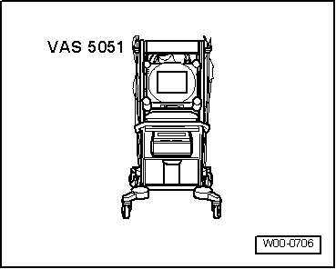
All functions which could previously be performed with V.A.G 1551/1552 can also be performed with the new tester VAS 5051 in the operating mode vehicle self-diagnosis. => Operating instructions for Vehicle Diagnosis, Testing and Information System VAS 5051. Special tools, workshop equipment, testers, measuring instruments and auxiliary items required
Test conditions: |
 |
|
|
 |
|
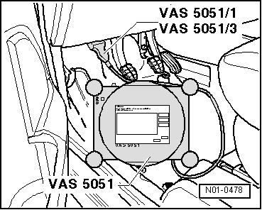
Connecting VAS 5051
After the fault reader has been connected:
Selecting operating mode:
Selecting vehicle system:
The control unit identification is indicated on the display. Note:
Selecting diagnosis function: All diagnostic functions available are indicated on the display.
Notes: The display zones in functions 04 - Basic setting or 08 - Read measured value block are shown from top to bottom. The following test sequences are for fault reader V.A.G 1551. Connecting V.A.G 1551 Special tools, workshop equipment, testers, measuring instruments and auxiliary items required
Note: The vehicle system tester V.A.G 1552 can be used instead of the fault reader V.A.G 1551, however a print-out is not possible. Work sequence
After the fault reader has been connected:
Notes:
=> Current flow diagrams, Electrical fault finding and Fitting locations binder
=> Fault reader operating instructions
|
| → Indicated on display: |
|
|||
|
* Appears alternately
|
| → The control unit identification is indicated on the display, e.g.: |
|
||
|
| → Indicated on display: |
|
||
|