seat Workshop Repair Guides

SEAT Workshop Service and Repair Manuals

Measured value blocks > < Reading readiness code
Motronic injection and ignition system (0.2 l engine)
Readiness code
Generating readiness code
 
N26-0481

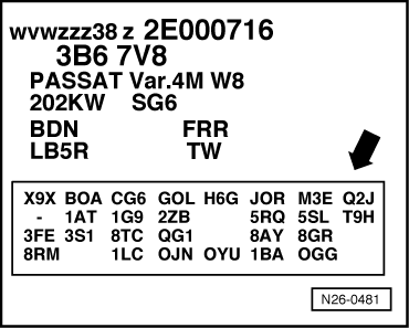
→ Only vehicles 05.01 ▸ and exhaust Pr. No. 0GG

=> Vehicle data plate

Special tools, workshop equipment, testers, measuring instruments and auxiliary items required

  • ◆ Fault reader V.A.G 1551 (or vehicle system tester V.A.G 1552) with cable V.A.G 1551/3

Test conditions

  • ● The battery voltage must be at least 11.5 V.
  • ● The fuel tank must be filled at least a 1/4.
 
N01-0485
  • ● → All fuses must be OK.
  • ● The signal from brake light switch and brake pedal switch and if necessary clutch pedal switch must be OK.
  • ● Intake air temperature less than 70°C
    =>display group 04, display zone 4
  • ● Coolant temperature must be at least 80 °C, =>display group 04, display zone 3.

Work sequence

  • ‒ Connect fault reader V.A.G 1551 (V.A.G 1552). Start engine and select "Address word" 01 of engine control unit. When doing this the engine must be running at idling speed.
    (Connecting fault reader and selecting engine control unit .)

Work step 1: Interrogate fault memory

 
→ Indicated on display:
Rapid data transfer    HELP
Select function XX
  • ‒ Press keys 0 and 2 for function "Interrogate fault memory" and confirm entry with Q key.
 
→ The number of faults stored or "No fault recognised!" will be shown on the display.
X Faults recognised!

If a fault is stored:

  • ‒ Rectify faults printed out using fault table:
    SAE P0 or P2 codes=> Page 01-41

If no fault is stored:

  • ‒ Press ⇒key.

Work step 2: Erase fault memory

 
→ Indicated on display:
Rapid data transfer    HELP
Select function XX
  • ‒ Press keys 0 and 5 for the function "Erase fault memory" and confirm entry with Q key.
 
→ Indicated on display:
Rapid data transfer    ⇒
Fault memory is erased!
  • ‒ Press ⇒key.

Notes:

  • ◆ The readiness code is reset or erased each time fault memory is erased.
  • ◆ If the ignition is switched off between "Interrogate fault memory" and "Erase fault memory" the fault memory will not be erased.
  • ◆ Only work step 5 must be performed during a test drive.
  • ◆ Following the test drive, the engine must be left running for the subsequent steps.
  • ◆ If the overrun phase of 3 seconds has not been achieved then several short tests will not start.
  • ◆ In some steps, it is possible that a subsequent step will already have been successfully completed in the background. In this case, proceed with the next step.
  • ◆ The work sequence "Generate readiness code" can only be repeated when ignition is switched off briefly between tests.

Work step 3: Diagnosis of ageing of Lambda probe before catalyst (probe dynamics)

 
→ Indicated on display:
Rapid data transfer    HELP
Select function XX
  • ‒ Press keys 0 and 4 for the function "Initiating basic settings" and confirm entry with Q key.
 
→ Indicated on display:
Basic setting
Input display group number XXX
  • ‒ Press keys 2, 1 and 2 for "Display group number 212" and confirm entry with Q key.
 
→ Indicated on display:
(1...4 = Display zones)
Read measured value block    212    ⇒
    1    2    3    4    
  • ‒ Increase and maintain engine speed between 2400...3000 rpm.
  • ‒ Observe display in display zone 4.
    If display indicates:     x x x 1 x x x x
    all test conditions are achieved and the test starts.
  • ‒ Allow engine to run at increased speed until
        Specification:     x x x x x 1 0 0
    appears in display zone 4 after about 40 seconds.

If the display does not indicate as described:

  • ‒ Press ⇒key.
  • ‒ Interrogate fault memory => Page 01-17.

If the display indicates as described:

  • ‒ Press C key.

Work step 4: Diagnosis of catalyst

 
→ Indicated on display:
Basic setting
Input display group number XXX
  • ‒ Press keys 2, 2 and 7 for "Display group number 227" and confirm entry with Q key.
 
→ Indicated on display:
(1...4 = Display zones)
System in basic setting    227    ⇒
    1    2    3    4    
  • ‒ Increase and maintain engine speed between 2400...3000 rpm.
  • ‒ Observe display in display zone 4.
    If display indicates:     x 0 0 0 1 x x x
    all test conditions are achieved and the test starts.

Note:

This process can take a few minutes.

  • ‒ Allow engine to run at increased speed until
        Specification:     x x x x x 1 0 0
    appears in display zone 4 after about 20 seconds.

If the display does not indicate as described:

  • ‒ Press ⇒key.
  • ‒ Interrogate fault memory => Page 01-17.

If the display indicates as described:

  • ‒ Press ⇒key.

Work step 5: Overrun diagnosis

 
→ Indicated on display:
Rapid data transfer    HELP
Select function XX
  • ‒ Press keys 0 and 8 for the function "Read measured value block" and confirm entry with Q key.
 
→ Indicated on display:
Read measured value block
Input display group number XXX
  • ‒ Press keys 0, 0 and 5 for "Display group number 5" and confirm entry with Q key.
  • ‒ Carry out test drive with a 2nd person to observe display.

Observe check conditions => Page 01-66.

Observe the valid safety precautions when carrying out a road test => Page 24-19.

Warning!
Observe the traffic regulations during the road test.
 
→ Indicated on display:
(1...4 = Display zones)
Read measured value block 5    ⇒
    1    2    3    4
  • ‒ Check whether the control unit recognises the operating mode "overrun" (display zone 4):
  • ‒ Accelerate vehicle in 2nd gear to an engine speed of approx. 3 000 rpm.
  • ‒ Then release accelerator pedal abruptly and allow the vehicle to coast in gear.
        Display: overrun

Note:

The display "overrun" must be achieved at least once for a period of 3 seconds.

If the display does not indicate as described:

  • ‒ Press ⇒key.
  • ‒ Interrogate fault memory => Page 01-17.

If an overrun phase of 3 seconds is achieved:

  • ‒ Press ⇒key.

Note:

The further work steps are performed with vehicle stationary.

Work step 6: Diagnosis of secondary air system

 
→ Indicated on display:
Rapid data transfer    HELP
Select function XX
  • ‒ Press keys 0 and 4 for the function "Initiating basic settings" and confirm entry with Q key.
 
→ Indicated on display:
Basic setting
Input display group number XXX
  • ‒ Press keys 0, 7 and 7 for the "Display group number 77" and confirm entry with Q key.
 
→ Indicated on display:
(1...4 = Display zones)
System in basic setting    77    ⇒
    1    2    3    4    
  • ‒ Allow engine to run at idling speed until the display in display zone 4 shows the result of the short test.
        Specification: "Syst. OK."

If the display does not indicate as described:

  • ‒ Press ⇒key.
  • ‒ Interrogate fault memory => Page 01-17.

If the display indicates as described:

  • ‒ Press C key.

Work step 7: Diagnosis of activated charcoal filter system (tank venting system)

 
→ Indicated on display:
Basic setting
Input display group number XXX
  • ‒ Press keys 0, 7 and 0 for "Display group number 70" and confirm entry with Q key.
 
→ Indicated on display:
(1...4 = Display zones)
System in basic setting    70    ⇒
    1    2    3    4    

When the diagnosis is initiated by the engine control unit the display in display zone 4 jumps from "Test OFF" to "Test ON"

  • ‒ Run engine at idling speed until the display in display zone 4 shows the result of the short test.
        Specification "TBV OK"

If the display does not indicate as described:

  • ‒ Press ⇒key.
  • ‒ Interrogate fault memory => Page 01-17.

If the display indicates as described:

  • ‒ Press ⇒key.

Work step 8: Exhaust gas recirculation system diagnosis

 
→ Indicated on display:
Rapid data transfer    HELP
Select function XX
  • ‒ Press keys 0 and 8 for the function "Read measured value block" and confirm entry with Q key.
 
→ Indicated on display:
Read measured value block
Input display group number XXX
  • ‒ Press keys 2, 3 and 5 for the "Display group number 235" and confirm entry with Q key.
 
→ Indicated on display:
(1...4 = Display zones)
Read measured value block    235    ⇒
    1    2    3    4    
  • ‒ Observe display in display zone 4.
    If display indicates:     1 x x x x x x x
    all test conditions are achieved and the test can be started.
  • ‒ If the first position from the left is a "0", raise engine speed to 2400...3000 rpm and create a slight load. Create a load by switching on lights, rear window heater and air conditioning.
  • ‒ Allow engine to run at increased speed until
        Specification:     1 x x x x x x x
    appears in display zone 4 after about 10 seconds.

If the display indicates as described:

  • ‒ Press key 4 for the "Basic setting" function ("Exhaust gas recirculation system diagnosis" will be initiated)
 
→ Indicated on display:
(1...4 = Display zones)
System in basic setting    235    ⇒
    1    2    3    4    
  • ‒ Observe display in display zone 4.
  • ‒ Allow engine to run at idling speed until
        Specification:     x x x x x 1 0 0
    appears in display zone 4 after about 30 seconds.

Note:

The engine may run uneven (rough/hunt) during the test but this is normal as the exhaust gas recirculation valve is activated several times.

If the display does not indicate as described:

  • ‒ Press ⇒key.
  • ‒ Interrogate fault memory => Page 01-17.

If the display indicates as described:

  • ‒ Press C key.

Work step 17: Diagnosis of ageing of Lambda probe after catalyst (probe dynamics)

 
→ Indicated on display:
Basic setting
Input display group number XXX
  • ‒ Press keys 2, 2 and 5 for "Display group number 225" and confirm entry with Q key.
 
→ Indicated on display:
(1...4 = Display zones)
Read measured value block    225    ⇒
    1    2    3    4    
  • ‒ Observe display in display zone 4.

Note:

This test should have run in the background by this time.

If the display does not indicate as described:

  • ‒ Allow engine to run at idling speed for approx. 2 minutes until
        Specification:     x x x x x 1 0 0
    appears in display zone 4.

If the display does not indicate as described after waiting period:

  • ‒ Repeat work step 5 and then work step 9.

Note:

If an overrun phase of 3 seconds was not recognised, this short test will not run.

If the display does not indicate as described after repeating the work step.

  • ‒ Press ⇒key.
  • ‒ Interrogate fault memory => Page 01-17.

If the display indicates as described:

  • ‒ Press C key.

Work step 10: Diagnosis of Lambda probe after catalyst

 
→ Indicated on display:
Basic setting
Input display group number XXX
  • ‒ Press keys 2, 2 and 2 for "Display group number 222" and confirm entry with Q key.
 
→ Indicated on display:
(1...4 = Display zones)
Read measured value block    222    ⇒
    1    2    3    4    
  • ‒ Allow engine to run at idling speed until
        Specification:     x x x x x 1 0 0
    appears in display zone 4 after max. 2 minutes.

If the display does not indicate as described:

  • ‒ Press ⇒key.
  • ‒ Interrogate fault memory => Page 01-17.

If the display indicates as described:

  • ‒ Press C key.

Work step 11: Diagnosis of Lambda probe heating after catalyst

 
→ Indicated on display:
Basic setting
Input display group number XXX
  • ‒ Press keys 2, 2 and 0 for "Display group number 220" and confirm entry with Q key.
 
→ Indicated on display:
(1...4 = Display zones)
System in basic setting    220    ⇒
    1    2    3    4    
  • ‒ Allow engine to run at idling speed until
        Specification:     x x x x x 1 0 0
    appears in display zone 4 after max. 2 minutes.

If the display does not indicate as described:

  • ‒ Press ⇒key.
  • ‒ Interrogate fault memory => Page 01-17.

If the display indicates as described:

  • ‒ Press ⇒key.
  • ‒ Press keys 0 and 6 for the function "End output" and confirm entry with the Q key.
  • ‒ Switch off ignition.

Work step 12: Read out readiness code

  • ‒ Read readiness code=> Page 01-63

Measured value blocks > < Reading readiness code